EasyManua.ls Logo

Jeep UNIVERSAL CJ-2A - Page 142

Jeep UNIVERSAL CJ-2A
281 pages
Print Icon
To Next Page IconTo Next Page
To Previous Page IconTo Previous Page
Loading...
'
Jeep'
UNIVE
RSA
L
an
d
'Jeep'
DISPATCHER
Brushes
tha
t
ar
e
soldere
d to
the
fi.el
d
coi
l
shoul
d
be
unsolder
ed
an
d
th
e
loo
o m
th
e field
coi
l
lea
d
shoul
d
be
op
e
ne
d.
I
nse
rt
the
new
brush
pigtai
l to
it
s full
dep
th
in
the
loo
p.
Th
e
new
brush
lea
d
shoul
d be tig
htly
clinched in
the
te
rmina
l
and
the
n
sol
dered
to
mak
e a st
ron
g,
low-resista
nc
e
co
nne
c-
ti
on.
1-52.
Commutato
r
Ch
eck
the
com
mu
ta
tor
for
we
ar
an
d
discoloration
.
If
the
commutator
is
ro
u
gh
or
worn
the
armatur
e
shou
ld
be
removed
and the
co
mmu
tator
t
urn
ed
do
wn
in
a
latn
e.
1-53.
Armatur
e
V
isua
lly
ins
pect
th
e
arma
tu re for m
echa
nical
defects
befor
e
checkin
g for
shor
ted
or
grounde
d
coils.
Us
e a
set
of t
es
t
probes
for
te
s
ti
ng
ar
m
at
ur
e
c
ir
cuits.
To
te
st
the
ar
m
at
ur
es for
gro
un
ds,
tou
ch
one
poi
nt
of
th
e
test
p
robe
s
to
a
co
mmu
tator
segm
ent
and
to
uch
th
e
othe
r
point
to
the
core
or
shaf
t.
Do
no
t
to
uc
h
th
e
poin
ts
to
t he
bearin
g
surfa
ce
or
to
the
br
u
sh
surfa
ce as the
arc
forme
d
will
burn
the
smooth
finis
h.
If
the
lamp
lights
, the
coil
connecte
d
to
the
co
mmu
tator
segment
is
grounde
d .
To
t
est
for
shor
ted
a
rmatur
e coils, a growler as
shown
in
Fi
g. 153
is
necessary.
Th
e
armatur
e is
place
d
against
th
e
core
and
a s
te
el
strip
is
hel
d
on
the
armature.
The
growler
is
th
en
energized
and
the
armature
rotated
slowly
by
hand.
If
a
shorte
d
coil
is
present,
the
stee
l
strip
will
become
magne
-
tized
and
will
then
vibrat
e.
1
-54
. Field
Coil
s
Using
test
probes
,
check
the
field coils
for
both
g
roun
d
and
open
circuits.
To
test
for
ground,
place
one
probe
on
the
motor
frame
or
pole
piece
and
touch
the
oth
er
probe
to
the
field coil
ter
minals
.
If
a
ground
is
presen
t,
th
e
lamp
will
light
.
To
test
for
open
circuits.
place
the
probes
on
the
field coil
terminal
and
on
an
insula
t
ed
brush.
If
the
light
does
no
t
light
,
the
coil is
open
circuited
.
1-55.
Bru
sh
Hold
er
In
s
pection
Using
test
probes,
touch
the
insulated
brush
holder
with
one
probe
and
a
convenient
ground
on
the
co
mmut
ator
end
head
with
the
oth
er
probe.
If
the
lamp
lights,
it
indicates
a
groun
ded
brush
holder.
1-56. A
sse
mbly
of
Start
i
ng
Motor
When
assembling
absorbent
bronze
bearings,
al-
ways
use
th
e
proper
arbor
designed
to
give
the
proper
bearing
fit.
Soak
the
bearing
in
oil
before
assembl
in
g
in
the
bearing
bor
e.
Brushes
should
be
correctly
installed
and
connected
as
outlined
in
Par.
I-50
in
order
to
be
sure
of
proper
starting
motor
efficiency.
Soak
the
bearings
in
oil
and
give
the
bearing
seats
a
light
coating
of
oil.
1-57.
Bench
Test
The
motor
should
first
be
checked
to
see
that
the
free
runnin
g volt
ag
e
and
c
ur
rent
are
within
s
pe
ci
fi
-
ca
tions. T o
tes
t, c
onnec
t
the
moto
r
to
a
ba
tt
er
y.
amme
t
er
an
d vol
tmeter.
If
the
c
urren
t
is
too
high
check
the
bearing
al
ignmen
t
and
end
play
to
ma
ke
su
re
th
ere is no
bi
nding
or
in
terfere
nc
e.
Using
a
sp
ri
ng
scale
and
torqu
e
arm
check
t
he
s
tall
t
orqu
e
to
s
ee
that
t he
moto
r is
prod
uc
in
g i
ts
ra
te
d
cr
an
k-
ing
power
.
Th
e
stall
t
or
que
wi
ll
be
the
produc
t
of
the
sprin
g scale
re
ading
and
th
e
lengt
h
of
th
e
ar
m
in feet.
If
th
e
to
rque
is n
ot
up
to
sp
ec
ifications
check
the
s
eati
ng
of the b
rushe
s
on
th
e
com
mu
ta
tor
and
the
in
te
rna
l
conne
ct
ion
of
the
mo
tor
f
or
hi
gh
res
istanc
e.
The
Ben
dix
Driv
e
shou
ld
be
che
ck
ed
for
c
or
rec
t
opera
tion.
Th
e B
endix
pinio
n
shoul
d be
check
ed
to
see
tha
t it
shi
fts
w
hen
the
m
otor
is
operate
d
un
der
no
loa
d
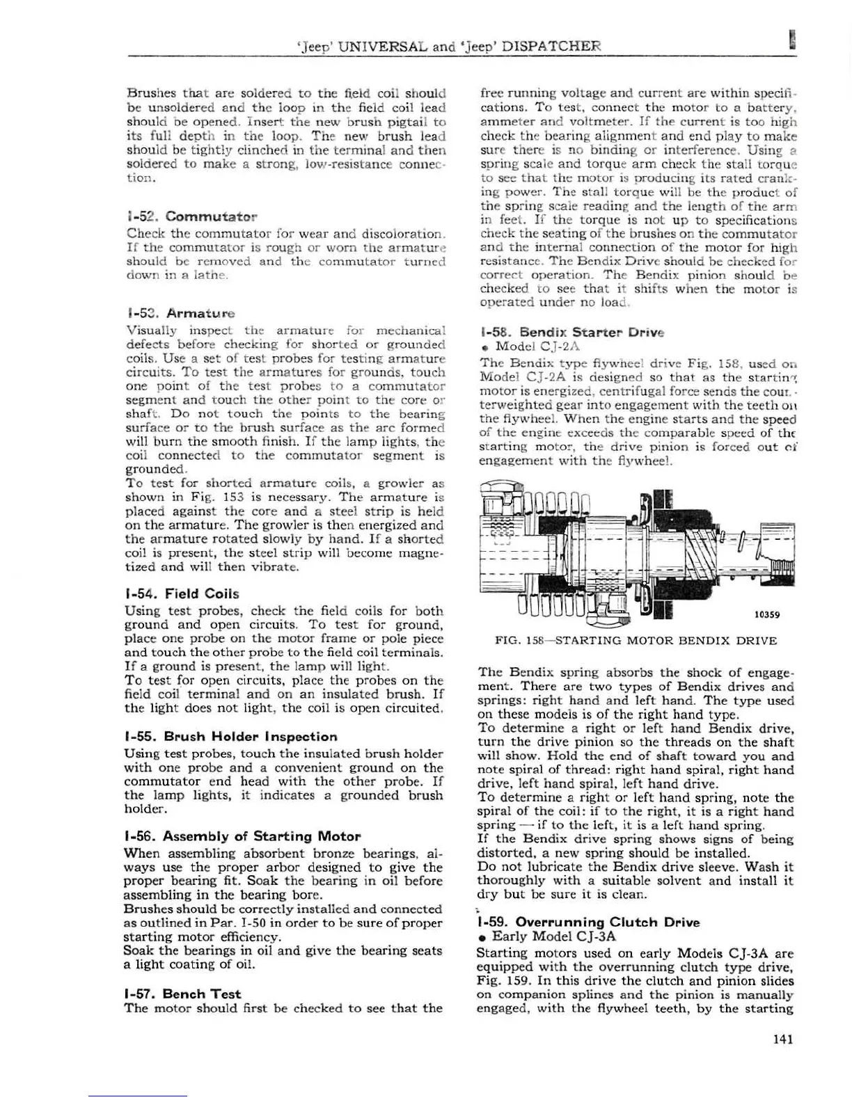
1-
58_
Bendix
Starte
r Drive
•
Mod
el
CJ-2
A
Th
e B
endix
t
yp
e fly
wn
ee
l
drive
Fi
g. 158,
us
ed
Oh
Mode
l CJ-2A is
design
ed
so
tha
t
as
th
e s
tart
in
":
m
otor
is
en
ergized
, cen
tr
ifugal force
sends
the
cour . .
terweighted
gear
into
en
g
agemen
t
with
the
teeth
on
the
flywheel.
When
t
he
e
ngin
e s
ta
rts
and
the
speed
of
the
e
ngin
e ex
ceeds
the
co
mparabl
e s
pee
d
of
the
st
artin
g
mo
tor,
th
e
drive
pinion
is forced
out
c:i
engagemen
t
with
th
e fly
wh
eel.
FIG.
158-
ST
ARTING
MOTOR
BENDIX
DRIVE
The
Bendix
spring
absorbs
the
shock
of
engage
-
men
t.
There
are
two
types
of
Bendix
drives
an
d
springs:
right
hand
and
left
hand.
The
type
use
d
on
these
m
odels
is
of
the
right
hand
type.
To
determine
a
right
or
left
hand
Bendix
drive,
turn
the
drive
pinion
so
the
threads
on
the
shaft
will
show.
Hold
the
end
of
shaft
toward
you
and
note
spiral
of
thread:
right
hand
spiral,
right
hand
drive,
left
hand
spiral,
l
eft
hand
drive.
To
determine
a
righ
t
or
left
hand
sp
ring,
note
the
spiral
of
the
coil:
if
to
the
right,
it
is a
right
hand
spring
-
if
to
the
left,
it
is
a
left
hand
sprin
g.
If
the
Bendix
drive
spring
shows
signs
of
being
distorted,
a
new
spring
should
be
installed.
Do
not
lubricate
the
Bendix
drive
sleeve.
Wash
it
thoroughly
with
a
suitable
solvent
and
install
it
dry
but
be
sure
it
is
clean.
1-59.
Overrunning
Clutch
Drive
•
Early
Model
C]-3A
Starting
motors
used
on
early
Mod
els
CJ
-3A
are
eq
uip
ped
with
the
overrunning
clutch
type
drive,
Fig.
159.
In
this
drive
the
cl
utch
and
pinion
slides
on
companion
splines
and
the
pinion
is
manually
engaged,
with
the
flywheel
teeth
,
by
the
starting
141