EasyManua.ls Logo

Jeep UNIVERSAL CJ-2A - Page 143

Jeep UNIVERSAL CJ-2A
281 pages
Print Icon
To Next Page IconTo Next Page
To Previous Page IconTo Previous Page
Loading...
I
ELECT
RICAL
SYSTEM
1
086
7
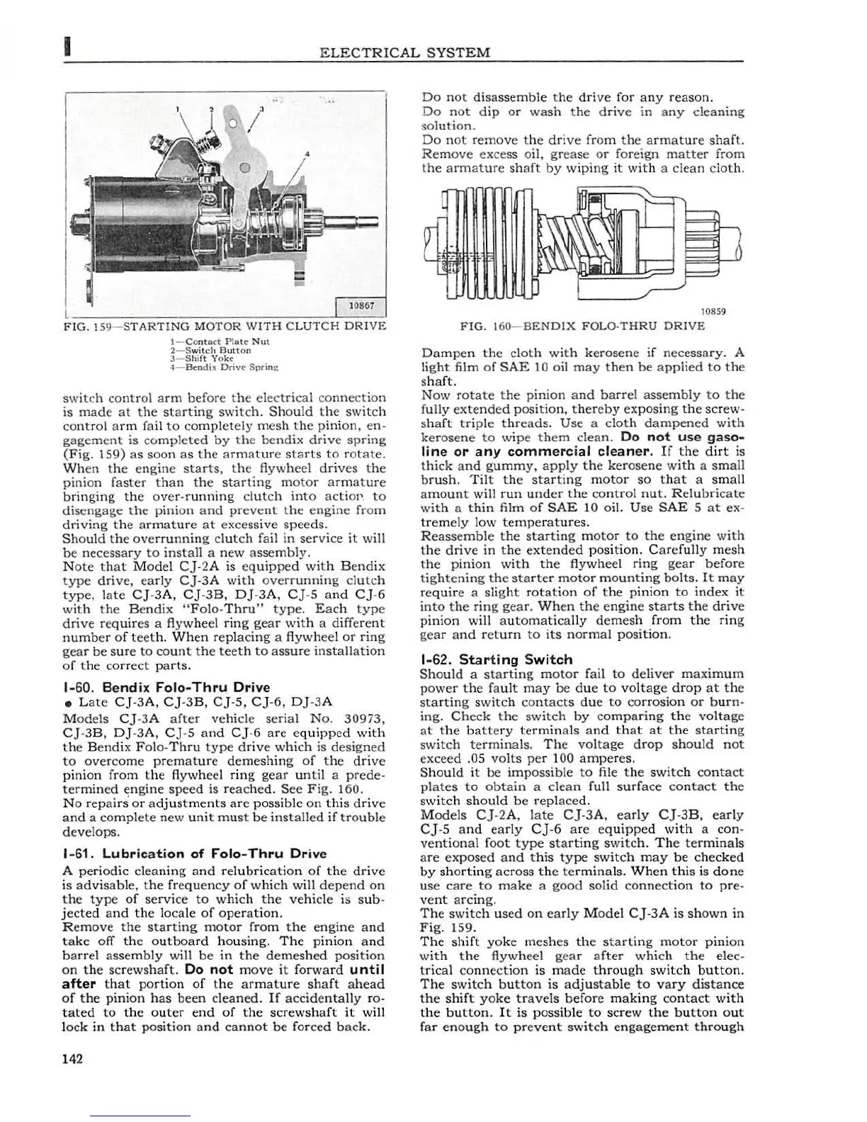
FIG.
!59-
STARTING
MO
TOR
WITH
CLUTCH
DRIVE
1-
Co
nt
oct
Pl
at
e
Nut
2-
Swit
ch
Butto
n
3
Sh
irt
Yoke
4-
Bcndix
Orlvc
Spri
n
c.
swit
ch co
ntrol
arm
befor
e
the
e
lectrical
co
nne
c
tion
is
made
at
the
st
a
rting
switch.
Should
the
switch
cont
rol a
rm
fail
to
completely
mesh
the
pin
i
on,
en-
gagement
is
co
mpl
et
ed
by
the
bendix
drive
spring
(Fig
. 1
59)
as
soon
as
th
e
armat
ur
e
starts
to
ro
tate.
Wh
en t
he
engin
e
starts
,
th
e flywheel
driv
es
the
pinion
faster
than
the
starting
motor
armature
bringing
the
over-running
clutch
int
o
actioP
to
disengage
th
e
pinion
and
prevent
t
he
engi
ne
from
driving
the
armature
at
excessive
speeds.
Sh
o
uld
the
overrunning
clutch
fail
in
service it will
be
nec
essa
ry
to
install
a new
assembly.
Note
that
Model
CJ-2A
is
eq
uipped
with
Be
ndix
type
drive,
ea
rly
CJ-3A
with
overrunning
clutch
type,
late
CJ-3A,
C]
-3B,
Dj-3A,
C]-5
a
nd
CJ
-6
with
the
B
endix
"Folo-
Thru
"
type.
Each
ty
pe
drive
re
quires
a flywheel
ring
gear
w
ith
a diffe
rent
number
of
teeth.
When
replacing
a flywheel
or
ring
gear
be
sure
to
count
the
teeth
to
assure
installation
of
the co
rrect
parts.
1-
60.
Bend
ix F
olo-Thru
Drive
•
Lat
e
CJ·3A,
CJ
-
3B,
C]-5,
C]-6
,
DJ
-3
A
M
ode
ls
CJ
-3
A
after
ve
hi
cle
serial
No
. 30973,
CJ
-3B,
DJ-3A,
C]
-5
and
CJ
-6
are
e
qu
ipped
with
the
Bendix
Folo-
Thru
type
drive
wh
ich is desi
gn
ed
to
overcom
e
prematur
e
demeshing
of
the
drive
pinion
from
the
flywheel
rin
g
gear
until
a
prede
-
termined
engine
speed
is
reached.
See
Fig.
160.
No
repairs
or
ad
ju
stments
are
poss
ible
on
this
dr
i
ve
and
a
comp
l
ete
new
unit
must
be
installed
if
trouble
develops.
1-61
.
Lubric
a
tion
of
Folo-
Thru
Dri
ve
A
periodic
cleaning
and
relubrication
of
the
drive
is
ad
visable,
the
freque
n
cy
of
which
will
depend
on
the
type
of
service
to
which
the
vehicle
is
sub
-
jected
and
the
locale
of
operat
io
n.
R
emove
the
starting
motor
from
the
engine
and
take
off
the
outboard
housing.
The
p
inio
n
and
barrel
assembly
will
be
in
the
demeshed
position
on
the
screwshaft.
Do
not
move
it
forward
until
after
tha
t
port
i
on
of
the
armature
shaft
ahead
of
the
pinion
has
been
cleaned.
If
accidentally
ro-
tated
to
th
e
outer
end
of
the
screwshaft
it
will
lock
in
that
position
and
cannot
be
for
ced
back.
1
42
Do
no
t
disassemble
the
drive
for
any
reason
.
Do
not
dip
or
wash
t
he
d
riv
e in
any
clea
nin
g
sol
uti
on
.
Do
no
t
remove
the
drive
fro
m the
armature
shaft
.
Rem
ove
excess oil,
grease
or
foreign
matter
from
t
he
armature
sh
a
ft
by
wi
ping
it
wit
h a
clean
c
loth
.
10859
FIG.
160- B
ENDIX
FOLO·THRU
DR
IV
E
Dampen
the
cloth
with
kerosen
e
if
necessary.
A
lig
ht
film
of
SAE
10 oil
may
then
be
ap
plied
to
the
s
haft
.
Now
rotat
e t
he
pi
nion
a
nd
barrel
assembly
to
the
fully
extended
position,
thereby
exposing
the
sc
rew
-
sha
ft
tr
iple
threads.
Use
a
cloth
dampened
with
kerosene
to
wipe
t
hem
clean.
Do n
ot
u
se
gaso-
line
or
a ny
commercial
clean
e
r.
If
the
dirt
is
t
hick
and
gummy,
apply
the
kerosene
w
ith
a
small
brush.
Til
t
the
sta
r
ting
moto
r
so
th
at
a
small
a
mount
will
run
under
the
cont
rol
nut.
Relubricate
with
a
thin
film
of
SAE
10
oi
l.
Use
SAE
5 at
ex
-
tremely
l
ow
temperatu
res.
Reass
e
mbl
e
the
sta
rt
ing
motor
to
the
engine
with
the
drive
in t
he
exte
nded
position.
Car
ef
ully
mesh
t
he
pinion
wi
th
the
flywheel
ring
gear
before
t
ightening
the
starter
motor
mounting
bolts.
It
may
require
a
slight
rotation
of
the
p
inion
to
index
it
into
the
ring
gear.
Wh
en
the
engine
starts
the
drive
pin
ion will
automatically
demesh
from
the
ring
ge
ar
and
r
et
urn
to
its
normal
position.
1
-62
.
Star
t
ing
Sw
it
ch
Should
a s
ta
rt
ing
motor
fail
to
delive
r
maximum
power
the
fault
may
be
due
to
voltage
drop
at
the
sta
rtin
g
switch
contacts
du
e
to
cor
rosi
on
or
burn-
ing
.
Check
the
switch
by
co
mp
aring
the
voltage
at
th
e
battery
te
rmin
als
and
th
at
at
the
starting
switch
terminals.
Th
e
voltage
drop
should
not
exceed
.OS
volts
pe
r 100
amperes.
Should
it
be
im
possib
le
to
file
the
switch
contact
plates
to
obtain
a
clean
full
surface
contact
th
e
sw
i
tch
should
be
repla
ced
.
M
ode
ls
CJ
-2A,
late
CJ
-3A,
early
C]
-3
B ,
early
C]
-5
and
early
CJ-6
a
re
e
quipped
wit
h a
con
-
vent
i
ona
l
foot
type
starting
switch.
The
terminals
a
re
exposed
and
this
type
switch
may
be
checked
by
sh
orting
ac
ross
the
terminals.
Whe
n t his is
don
e
use
care
to
make
a
good
solid
connec
tion
to
pre-
vent
arc
ing.
The
switch
used
on
early
M
odel
CJ
-
3A
is
shown
in
Fig.
159.
The
shi
ft
yoke
meshes
the
st
arting
motor
pinion
wit
h t
he
flywheel
gea
r
after
which
the
elec-
tr
ical co
nn
ect
ion is m
ade
t
hrough
swi
tc
h
button.
Th
e
switch
button
is
ad
justable
to
vary
distance
the
shift
yoke
travels
before
making
contact
with
t
he
button
. It
is
possib
le
to
screw
the
bu
tton
out
far
enough
to
pr
event
switch
engagement
through