EasyManua.ls Logo

Jeep UNIVERSAL CJ-2A - Page 145

Jeep UNIVERSAL CJ-2A
281 pages
Print Icon
To Next Page IconTo Next Page
To Previous Page IconTo Previous Page
Loading...
B
ELECTRICAL
SYSTEM
connect
the
ga
u
ge
to
a
new
fuel
tank
sending
uni
t
whi
ch
has
been
grounded
to
the
vehicle.
If
the
gaug
e
registers
inc
orrec
tly
when
operating
the
new
uni
t,
repla
ce
th
e
gauge;
if
correctly,
replace
th
e
sendin
g
uni
t.
Should
a new fuel t
ank
uni
t
no
t
be
available
for
testing, use a 6- or
12-volt
test
ligh
t
in
its
pla
ce.
Wne
n
the
gauge
is
operating
co
rr
ectly,
the
poin
te
r
will
mov
e
approximatel
y
three-quar
te
rs
across
the
dia
l.
On
some
vehicles,
th
e
tempera
t
ur
e
gauge
m
ay
register
on
or
close
to
the H
(hot
) m
ark
wh
en
coolant
te
m
perature
is
190°F . to
200°F.
[88°C. a
93
°C
.].
In
such
cases, a
25-ohm,
!-
wat
t resis
tor
ma
y
be
installed
on
the
temper
at
ur
e
gauge
whi
ch
will
place
the
point
er
just
beyond
the
center
m
ark
at a cool
ant
temperature
of 19
0°F.
to
200°F.
Ins
tall
the
re
s
istor
between
the
two
ter
mina
ls
on
the
back
of
th
e
gaug
e.
Insulat
e
the
exposed
leads
of
th
e
resis
tor
wi
th
electrical
tap
e.
If
th
e oil
pre
ssur
e
indi
cator
does
n
ot
indicat
e
cor
-
rect
ly
, first
check
the
ligh
t
bulb.
Nex
t
check
all
connections
and
lea
d wires.
If
,
after
all
possible
defe
cts
ar
e
cor
re
cted
,
the
indica
tor
light
does
no
t
go
on
and
off
pro
perly
,
then
the
diaphragm
type
swit
ch
in t he
cylinder
block
should
be
replac
ed
.
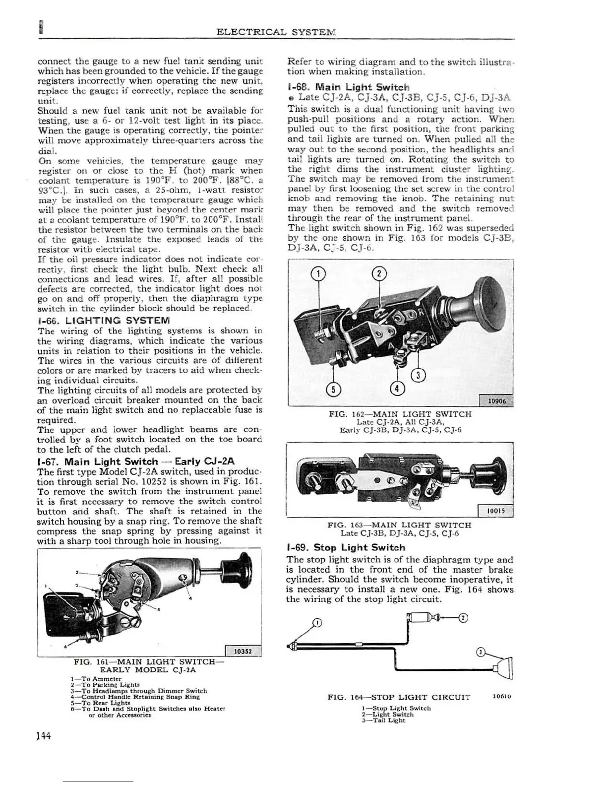
1-66.
LIGHTING
SYSTEM
The
wirin
g
of
the
lighting
systems
is
shown
in
the
wiring
diag
ra
ms
,
which
indicate
the
various
uni
ts
in
relation
to
their
positions
in
the
vehicle.
Th
e wires
in
th
e
various
circ
uits
are
of
different
colors
or
are
marked
by
trace
rs
to
aid
when
che
ck-
ing
individua
l
circuits
.
T
he
lighting
circuits
of
all
models
are
protected
by
an
overload
circuit
breaker
mounted
on
the
bac
k
of
the
main
ligh
t
switch
and
no
replaceable
fuse
is
requir
ed.
Th
e
upper
and
lower
headlight
beams
are
con
-
trolled
by
a fo
ot
sw
i
tch
l
ocated
on
the
toe
board
to
the
left
of
the
clutch
peda
l.
1-67.
Main
Light
Switch
-
Early
CJ
-
2A
Th
e first
type
M
odel
CJ
-2
A
switch
,
used
in
produ
c-
tion
through
serial
No.
10252
is
shown
in
Fig.
161.
To
remove
the
switch
from
the
instrum
ent
panel
it
is
first
necessary
to
remove
the
switch
control
bu
tton
and
shaft.
Th
e
shaf
t
is
retained
in
the
switch
housing
by
a
snap
ring.
To
remove
the
shaf
t
compress
the
snap
sprin
g
by
pressing
agains
t
it
with
a
sharp
tool
th
rou
gh
hole
in
h
ous
in
g.
6
}4
4
FIG.
1
61
-
MAIN
LIGHT
SWITCH
-
EARLY
MODEL
CJ-2A
I -
To
Ammeter
2-To
Parkin
g
Lighta
3-To
Headl
amps
through
Dimmer
Sw
itch
4-<:0<>trol
H
andle
Re
taining
Snap
Ring
5-To
Rear
Li~th
ts
6-
To
Dash
ond
Stoplight
Switches
al
so
Hea
ter
or
other
Acceuories
10352
R
efer
to
wirin
g
diag
ra
m
an
d
to
the
switc
h
illust
ra-
tion
w
hen
making
ins
tallation.
1
-6
8. M
ain
Light
Switc
h
e
Late
CJ-2A
,
CJ-3A,
CJ-3B
,
CJ-5,
CJ-
6,
DJ-3
A
Thi
s
swit
ch
is a du
al
functioning
unit
havin
g two
push-pu
ll
positio
ns
and
a
rotary
a
ction.
Whe
n
pu
lled
ou
t
to
the
first
position,
the
front
parkin
g
and
tai
l lights
are
turned
on.
Wh
en
pulled
all
th
e
wa
y
ou
t
to
the
seco
nd
position
,
the
headlights
and
tai
l
lights
are
t
urne
d
on.
Rota
t
in
g the
switch
to
the
right
dims
the
instrument
cluste
r
lighting
.
The
swi
tch
may
be
removed
from
the
instrumen
t
panel
by
first
loosening
th
e
set
sc
re
w
in
the
contro
l
knob
and
removing
the
kn
ob.
The
re
tai
nin
g
nu
t
ma
y th
en
be
removed
and
the
swit
ch
remove
d
through
the
r
ear
of
the
i
ns
tr
umen
t
pan
el.
Th
e
ligh
t
switch
shown
in
Fig.
162
was
supersede
d
by
the
one
s
hown
in
Fig.
163
for
models
CJ-3B
,
D
J-
3A,
C
J-5,
CJ-
6.
F I
G.
1
62-
MAIN
LIGHT
SWITCH
L
ate
CJ-2A,
All
CJ-
3A,
Earl
y
Cj-3B,
DJ-
3A
.
CJ
-5
,
CJ-6
FIG.
163-
MAIN
LIGHT
SWITCH
Lat
e
Cj-3B,
Dj-3A,
CJ-5,
CJ-6
1-69.
Stop
Light
Switch
T
he
stop
light
switch
is
of
the
diaphragm
type
and
is
l
ocated
in
the
front
en
d
of
the
mas
ter
brake
cylinder.
Should
the
switch
become
inop
er
ative
,
it
is
necessary
to
install
a
new
on
e.
Fig.
164
shows
the
wiring
of
th
e
stop
light
cir
cui
t.
FIG.
164-
STOP
LI
GHT
CIRCUIT
1-Sto
p
Light
Switch
2-
Li
ght
Switc
h
3-
Tail
Li
ght
10610