EasyManua.ls Logo

Jeep UNIVERSAL CJ-2A - Page 146

Jeep UNIVERSAL CJ-2A
281 pages
Print Icon
To Next Page IconTo Next Page
To Previous Page IconTo Previous Page
Loading...
'J
eep'
UNIVERSAL
and
'Jeep
'
DISPATCHER
1-70.
PR
IMAR
Y C
IRCUI
T
Before
t
esting
t
he
p
rim
a
ry
circuit
,
mak
e
ce
rta
in
that
t
he
ba
ttery
is
satisfactory
or i
nstall
a
fully
c
harged
ba
tter
y f
or
the
pri
mary
ci
rcuit
te
sts.
Also,
c
heck
the
starter
motor
f
or
excessive
voltage
drop
a
nd
c
heck
t
he
starter
motor
i
tself
for
exce
ssive
d
raw.
a .
Measure
t
he
vo
lta
ge
at
the
coil
prima
ry
te
rmi-
n
als
while
cranking
t
he
engine
with
th
e
starter
motor.
If
t
he
vo
l
tage
is l
ess
t
han
4
72
volts
with
6-
v
olt
sy
stem
or
9
volts
with
12
-
volt
system
the
t
roubl
e will be
fo
und
in t
he
p
rimary
c
ircuit.
If
t
here
is
no
voltage
at
all,
check
for a
break
in
the
p
rimary
c1r
cui
t ,
possibly
in
the
coil p
ri
mary
wind-
ing
.
~
-
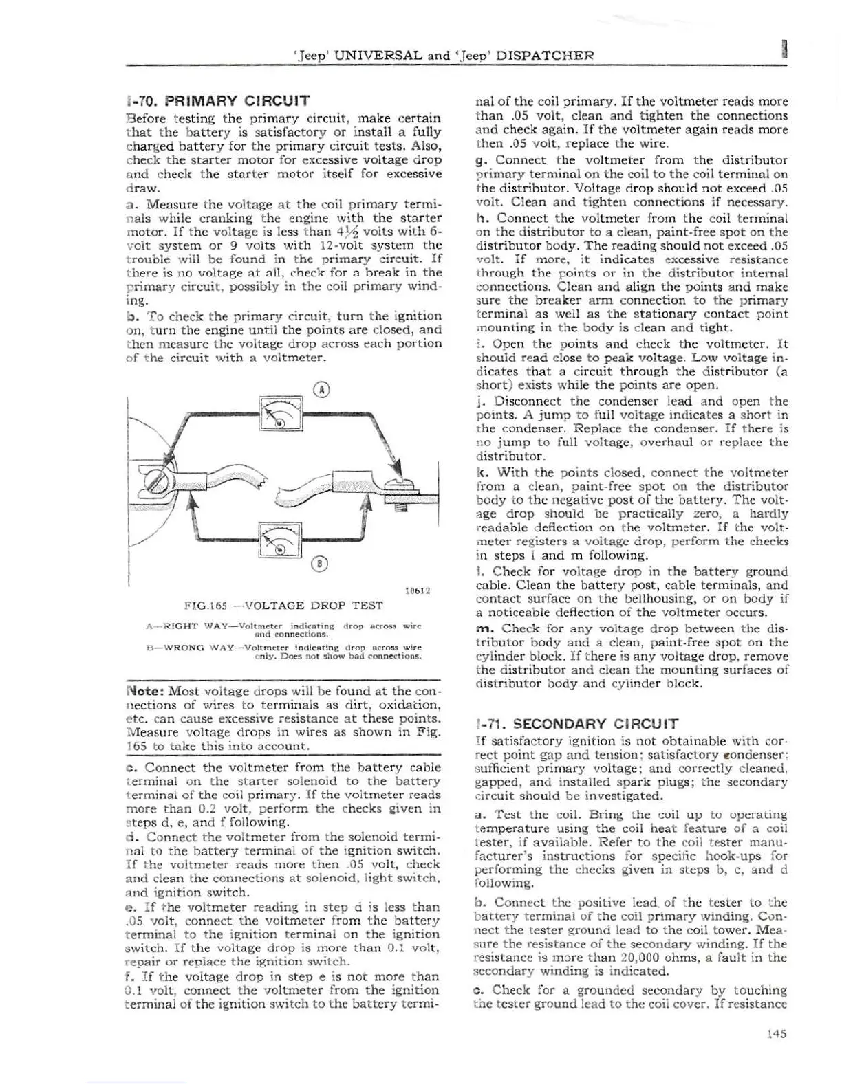
To
check
the
pri
mary
ci
rcuit
,
turn
t
he
i
gnition
on, t
urn
t
he
eng
ine
until
the
po
in
ts
are
cl
osed,
and
t
hen
measu
re
t
he
volt
ag
e d
rop
acro
ss
eac
h
portio
n
of
t
he
ci
rcuit
with
a v
oltmeter
.
10612
FI
G.
I65
-VO
LTAGE
D
ROP
T
EST
A-
RI
GH
T
WAY-V
o
ltmeter
i
odicoting
d
rop
ocro»
wire
und
co
nnec
tio
ns.
B-
WRONG
WAY-Vo
ltm
eter
!ndicating
d
rop
ocross
wire
o nly .
Doe'S
no
t
show
b
ad
co
nne
ctions.
N
ote:
Most
voltage
d
rops
will
be
found
at
the
co
n-
n
ections
of
wires
to
terminals
as
di
rt
,
ox
idation,
e
tc
.
ca
n
cau
se
ex
cessive
re
sistance
at
these
points.
M
easure
v
oltage
drops
in
wires
as
shown
in
Fig.
165 to
take
this
i
nto
account.
c .
Connect
the
voltmeter
f
rom
t
he
battery
cable
t
erminal
on t
he
sta
rte
r
so
l
enoid
t o
the
bat
tery
t
er
minal
of
the
coil
primary.
If
the
voltmeter
reads
mo
re
than
0.2
volt,
p
er
fo
rm
the
c
hecks
given
in
s
teps
d,
e,
and
f following.
d .
Co
nne
ct
the
volt
me
ter
from
t
he
s
olenoid
termi-
ual
to
the
b
attery
t
ermina
l
of
t
he
1
gnition
switch.
If
t
he
voltmeter
read
s
more
th
en
.05
volt,
c
heck
and
cle
an
t
he
co
nne
ctio
ns
at
sol
enoid
, l
ight
switch,
and
i
gnition
switch
.
e.
If
t
he
voltmet
er
r
eading
in
step
d is l
ess
than
.05
vol
t ,
co
nnect
t
he
vol
tmeter
f
rom
t
he
battery
te
rmi
nal
to
the
i
gnition
term
inal
on t
he
ig
nit
io
n
s
witch.
If
t
he
vol
tage
drop
is
more
tha
n 0.1
vol
t ,
re
pa
ir
or r
eplace
the
igmtlon
switch.
f . If t
he
voltage
d
rop
in
s
tep
e is
not
more
th
an
0.1 rolt,
co
n
nect
the
vo
ltme
te
r
fro
m
the
ig
nition
t
erminal
of
the
igmtion
sw1tch
to
t
he
b
attery
t
ermi·
nal
of
the
coil pr
ima
r
y.
If
the
voltmeter
reads
more
tha
n .05
volt,
clean
and
t
ighten
the
co
nnec
tions
a
nd
check
again.
If
t
he
vo
ltmeter
again
reads
more
t
hen
.OS
volt,
replace
t
he
wire.
g.
Connect
t
he
voltmeter
f
rom
the
distrib
u
tor
!)
ri
mary
termi
na
l
on
the
coil
to
the
coil
terminal
on
t
he
di
s
trib
u
tor.
Voltage
dr
op
should
not
exceed
.05
vol
t.
Cl
ean
and
tig
hten
con
nections
if
necessary
.
h.
Co
nnec
t t
he
vol
tmeter
from t
he
coil t
erminal
on t
he
distributor
to
a
clean,
pai
nt
-free
spot
on
th
e
d
istributo
r
body.
The
reading
should
not
exceed
.OS
vo
lt.
If
more,
it
i
ndicates
ex
cessive
resi
stanc
e
t
hrough
the
points
or
in t
he
distributo
r
internal
con
nections.
Clean
and
align
the
po
ints
and
make
s
ure
the
breaker
a
rm
co
nnection
to
th
e p
rimar
y
t
erminal
as
well
as
t
he
stati
o
nary
contact
poi
nt
mo
unting
in
t
he
b
ody
is
clean
and
tight
.
L
Ope
n t
he
p
oints
and
c
heck
t
he
voltmeter.
It
s
hould
read
cl
ose
to
peak
voltage.
Low
voltage
in-
d
ica
te
s t
hat
a c
ircuit
t
hrough
t
he
d
istributor
(a
s
hort
) e
xists
while
the
poi
n
ts
are
open.
j .
Disco
nne
ct
th
e
co
ndenser
l
ead
a
nd
op
en
t
he
p
oints.
A
jump
to
f
ull
voltag
e
indicates
a s
hor
t in
t
he
co
ndenser.
Replace
t
he
condenser.
If
th
ere
is
no
j
ump
to
full
vol
tage
, o
verhaul
or
replace
the
d
istributo
r.
t<
.
With
t
he
p
oin
ts
clo
sed
,
connect
t
he
vol
tm
ete
r
f
rom
a cl
ean
,
pa
int
-f
ree
spo
t on
the
dist
ribu
tor
b
ody
to t
he
negative
post
of
the
battery.
T
he
volt-
age dr
op
sho
u
ld
be p
rac
t ically z
er
o, a
hardly
r
eadable
deflect
ion
on t
he
voltmeter.
If
t
he
vol
t-
meter
re
gi
sters
a
voltag
e
drop,
pe
rform
t
he
check
s
in
steps
1
and
m followi
ng.
I.
C
heck
f
or
voltage
d
rop
in
t
he
battery
g
roun
d
cable
.
Cl
ean
t
he
bat
ter
y
po
st,
cab
le
term
inals, a
nd
co
ntact
s
ur
fa
ce
on
the
b
ellhousing,
or
on
body
if
a
noticeable
deflectio
n
of
the
v
oltmeter
occ
urs.
m.
Check
for
any
voltage
drop
betwe
en
t
he
dis-
t
ributor
body
and
a
clean,
paint-f
ree
spot
on
the
cyl
inder
block.
If
t
here
is
any
voltage
drop,
remove
t
he
d
istribut
or
and
cl
ean
t
he
moun
ti
ng
surfaces
of
d
istributor
bo
dy
and
cyl
inder
bl
ock.
1-
71.
SECONDARY
CIRCUIT
If
satisfactory
i
gnition
is
not
obtainable
with
co
r-
r
ect
point
gap
and
tension
;
satisfactory
~ondenser
;
sufficient pri
mary
voltage;
and
co
rrectly
cl
eaned,
gapp
ed
, a nd i
nst
alled
s
park
plugs;
t
he
secondary
cir
cuit
should
be
in
vestigated.
a.
Te
st
t
he
coil.
Bring
t
he
co
il
up
to
op
t!rat
ing
t
emperature
us
ing
t
he
coil
he
at f
eature
of
a
co
il
t
ester,
if
av
ailab
le.
Refer
to
t
he
coil
te
ster
manu-
f
acturer
's
instructions
f
or
specific
ho
ok
-up
s
fo
r
perfo
rming
t
he
ch
ecks
gi
ven
in
step
s
b,
c,
and
d
f
ollowing
.
b.
Co
nn
ec
t
the
p
ositive
l
ead
. of t
he
t
ester
to t he
b
attery
t
erminal
of
t
he
coil prim
ary
wmd
ing
. Con-
nect
t
he
te
st
er
gro
un
d le
ad
to
t
he
c
oil
to
we
r.
Mea·
s
ure
t
he
resistance
of
the
secondary
wi
nding.
If
the
resi
stanc
e is
more
th
an
20,000
oh
ms
, a f
au
lt
in
th
e
se
conda
ry
wmding
is
ind
icated
.
c.
C
heck
for
a g
roun
ded
secondary
by
to
uching
t
he
t
es
ter
gr
ound
lead
to
th
e coil
cover.
If
res
istanc
e
145