EasyManua.ls Logo

Jeep UNIVERSAL CJ-2A - Page 208

Jeep UNIVERSAL CJ-2A
281 pages
Print Icon
To Next Page IconTo Next Page
To Previous Page IconTo Previous Page
Loading...
'Jeep'
UN
I
VERSAL
and
'Jeep'
D I
SPATCHER
N
a .
With
the
differential
positioned
as
shown
in
Fig.
263,
bounce
the
differential
lightly
on
a
flat
surface
so
the
differentia
l
gears
settle.
b.
Measure
the
clearance
between
side
gears
and
the
case
as
illustrated
.
c.
If
the
clearance
exceeds
.006",
add
shims
between
the
side
gears
and
the
case
.
To
bring
the
clearance
within
spec
ified
to
le
rance,
shims
in
these
thicknesses
are
available:
.004"
[0,10
mm
.], .
006"
[0,15
mm.],
.
008
" [0,20
mm.]
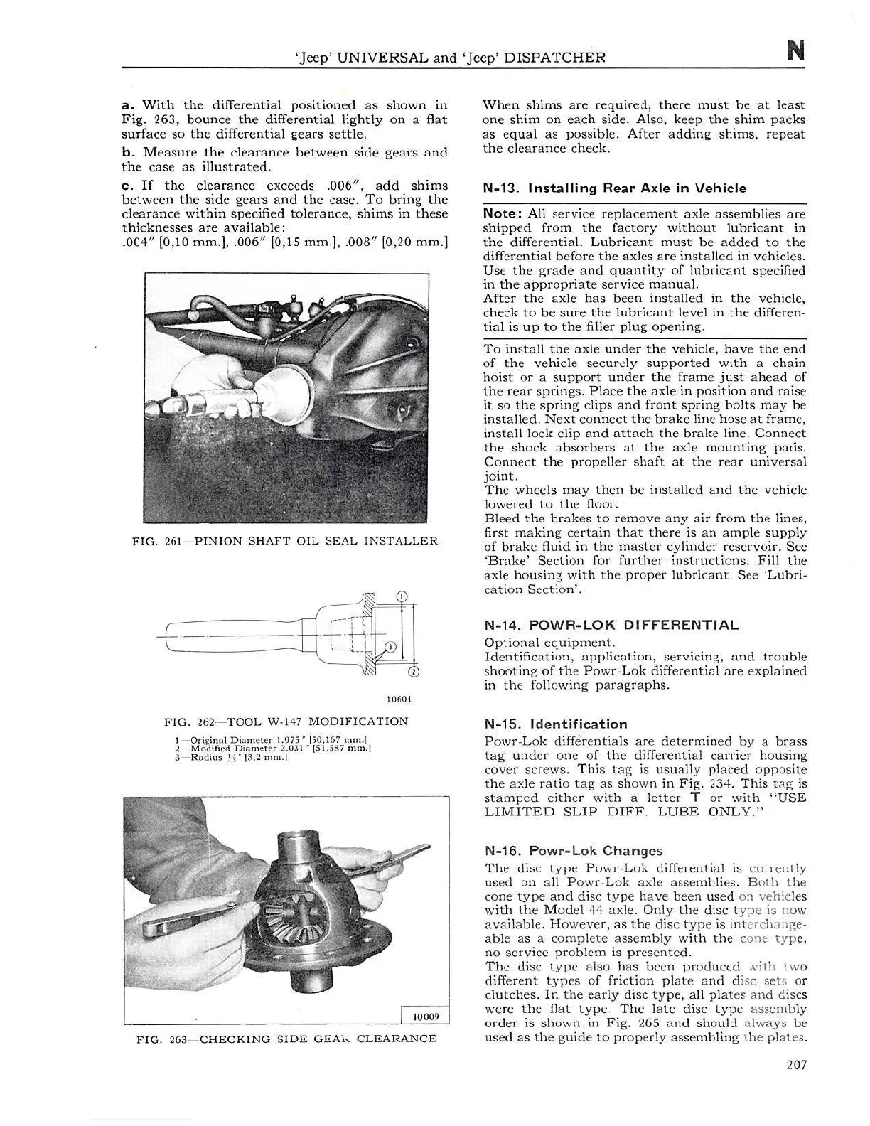
FIG.
261
-
PINION
SHAFT
OIL
SEAL
INSTALLER
10601
FIG.
262-
TOOL
W -
147
MODIFICATION
!-
Ori
g
in
al
Oi
a
met
er 1.975 •
isO,l67
mm.]
2- M o
difi
ed
Oinmcter
2.031 ' [
51.587
mm.
J
3- R
ad
iu
s JS" (3
.2
mm.l
FIG.
263-
CHECKING
SIDE
GEAi'
CLEARANCE
Wh
en
shims
are
required,
there
must
be
at
least
one
shim
on
each
side.
Also,
ke
ep
the
shim
pac
ks
as
equal
as
possib
le.
Af
ter
adding
shims,
repeat
the
clearance
check
.
N-13.
In
sta
lling
R
ea
r
Axle
in
Vehi
c
le
N
ote:
All
service
replacement
axle
assemblies
are
sh
i
pped
from
the
factory
without
lubricant
in
the
differentia
l.
Lubricant
must
be
added
to
the
differential
before
the
axles
are
installed
in
vehicles
.
Us
e
the
gr
ade
a
nd
quantity
of
lubricant
specified
in
the
appropriate
service
manu
al.
After
the
axle
h
as
been
inst
alled
in
the
vehicle,
check
to
be
sure
the
l
ubricant
level
in
the
differen-
tial
is
up
to
the
filler
plug
ope
ning.
To
install
the
axle
under
the
ve
hicle
, h
ave
the
end
of
the
vehicle
secur.::ly
supported
with
a
chain
hoist
or
a
support
under
the
fram
e
just
a
head
of
the
r
ea
r
springs.
Place
the
axle
in
position
and
raise
it
so
the
spring
clips
and
front
spring
bolts
may
be
installed.
Ne
xt
connect
the
brake
line
hos
e
at
fr
ame,
i
ns
ta
ll l
ock
clip
and
attach
the
brake
line
.
Conn
ect
the
shock
absorbers
at
the
axle
mounting
pads
.
Conn
ect
the
propeller
shaft
at
the r
ear
universal
joint.
Th
e
wheels
may
then
be
installed
and
the
vehicle
lowered
to
the
floor.
Bleed
the
brakes
to
remove
any
air
from
the
lines,
first
making
certa
in
that
there
is
an
amp
le
supp
ly
of
brake
fluid
in
the
m
aster
cylinder
reservoir.
See
'
Brake'
Section
for
fur
the
r
instructions.
Fill
the
ax
le
housing
with
the
proper
lub
ric
ant
. See
'Lubri
-
catio
n
Section'.
N-
1
4.
POWR
-LO
K
DIF
FER
EN
TI
AL
Op
tional
equipment.
Identification
,
applicat
ion, se
rvicing
,
and
trouble
shooting
of
the
Powr-Lok
diff
erentia
l
are
exp
lained
in
the
followi
ng
paragraphs.
N-15 . I
denti
f
icat
ion
Powr-Lok
differentials
are
determined
by
a
brass
tag
un
der
one
of
th
e
differential
carrier
housing
cover
screws
.
Thi
s
tag
is
usually
placed
oppos
ite
the
ax
le
ratio
tag
as
shown
in
Fig.
234
.
Th
is
t'lg
is
stamped
either
w
ith
a
letter
T
or
with
"USE
LIMITED
SLIP
DIFF.
LUBE
ONLY."
N-16
.
Powr
-Lok
C h
anges
Th
e
disc
type
Powr-Lok
differential
is
current
ly
used
on
all P o
wr
-Lok axle
assemblies
.
Both
t
he
cone
type
and
disc
type
have
been
used
on
vehicl
es
with
the
Model
44
axle
.
Only
the
disc
ty;Je is
no
w
avai
l
able
.
However,
as
the
disc
type
is
int
erc
h
ang
e-
able
as
a
comp
lete
assemb
ly
with
the
cone
typ
e,
no
service
problem
is
presented.
The
disc
type
also
has
been
produced
.vith t
wo
different
types
of
friction
plate
and
disc
set
s
or
clutches.
In
the
early
disc
type,
all
plat
es
and
di
scs
were
the
flat
type.
The
late
disc
typ
e
asse
mb
ly
order
is
shown
in
Fig.
265
and
should
alway
s be
used
as
the
gu
id
e
to
properly
assemblin
g t
he
pl
ate
s.
207