EasyManua.ls Logo

Jeep UNIVERSAL CJ-2A - Page 207

Jeep UNIVERSAL CJ-2A
281 pages
Print Icon
To Next Page IconTo Next Page
To Previous Page IconTo Previous Page
Loading...
N
REAR
AXLE
Install
pinion
nut
and
cotter
pin.
Then
install
axle
shafts
and
differenti
al
housing
cover.
Not
e:
To
drive
t
he
latest
type
pinion
shaft
oil
seal
,
the
diameter
of
the
recess
on
th
e
driving
end
of
To
ol W -147
must
be
2.031"
[51
,
59
mm.].
E
arly
production
W-147
tools
had a
recess
diameter
of
1.975" [50,15 mm.J.
If
necessary,
increase
the
diameter
of
the
tool
as
shown
in
Fig.
262 ,
so
that
it
can
be
used
to
drive
eith
er t
ype
seal
without
damaging
the
seal.
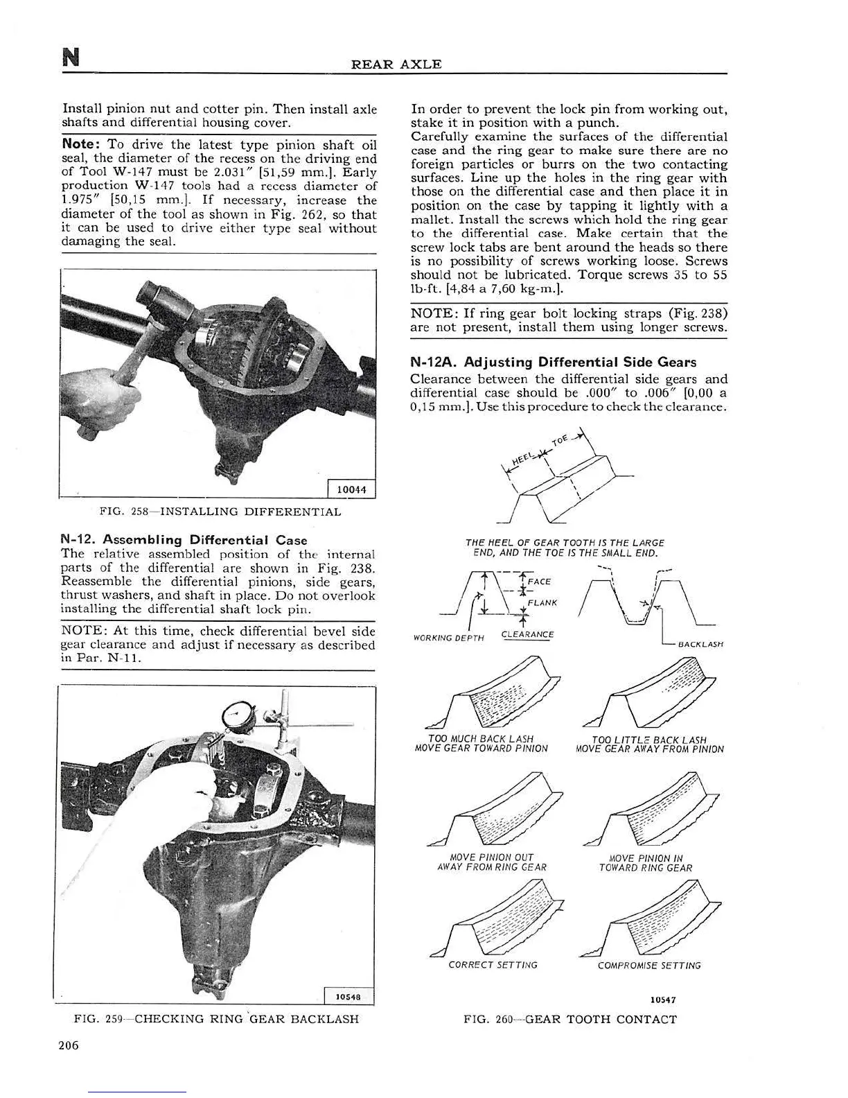
FIG
. 258-
INSTALL
IN
G
DIFFERENTIAL
N-12.
As
se
mbling
Diff
e
renti
al Case
The
relative
ass
e
mbled
position
of
th
e
int
e
rn
al
par
ts
of
th
e
differenti
al
a
re
shown
in
Fig.
238
.
Reassembl
e
the
differential
pinions
,
side
gears,
thrust
washers,
a
nd
shaft
in
place.
Do
not
ov
e
rlook
i
nst
alling
the
differential
shaft
l
ock
pin.
NOTE:
At
this
time
,
check
differential
bevel
side
gear
clearanc
e a
nd
adjust
if
nece
ss
a
ry
as
described
in
Par.
N-11.
FIG.
259
·-
CHECKING
RING
,
GEAR
BACKLASH
206
In
order
to
prevent
the
lock
p
in
from
working
out,
s
take
it
in
position
with
a
punch.
Carefully
examine
the
surfaces
of
the
differential
case
and
the
ring
gear
to
make
sure
there
are
no
foreign
particles
or
burrs
on
the
tw
o
contacting
surfaces
.
Lin
e
up
the
holes
in
the
ring
gear
with
those
on
the
differential
case
and
then
pl
ace
it
in
position
on
the
case
by
tapping
it
lightly
w
ith
a
mallet
.
Insta
ll
the
screws
which
hold
the
ring
gear
to
the
different
ial
case
.
Make
certain
th
at
the
s
crew
Jock
tabs
are
bent
around
the
heads
so
there
is
no
possibility
of
screws
wor
king
loose.
Screws
shou
ld
not
be
lubri
cated
.
Torqu
e
screws
35
to
55
lb
-
ft.
[4,84 a 7,60
kg-m
.].
NOTE:
If
ring
gear
bolt
locking
straps
(Fig.
238)
are
not
present,
install
them
usi
ng
longer
screws.
N-12A.
Adjusting
Dif
fe
rent
i
al
Sid
e
Gears
Clearance
between
the
different
ial
side
gears
and
diff
ere
ntial
case
should
be
.000"
to
.006" [0,00 a
0,15
mm.].
Use
th
is
procedure
to
check
th
e
clearance.
THE HEEL
OF
GE
AR
TOOTH
IS
THE LARGE
E
ND,
AND
THE
TOE
IS
TH
E S
MAll
END.
m~
-
fACE
_)
(L\
~
L
AN
K
W
OR
KI
NG
DEPTH CLEARANCE
TOO
MUCH
B
AC
K L
AS
H
MOVE
GEAR
TOWA
RD PINION
MOV
E PINION O
UT
AIV
AY
FRO
M RING
GEA
R
COR
RECT SETTING
--"',
-~
~H
TOO
LITTLE
BACK LASH
MOVE
GEAR
AWAY
FROM
PINION
MO
VE PINION IN
TO
WA
RD
R
ING
GEAR
COM
PR
OMIS
E SETTING
10547
F
IG.
260- -
GEAR
TOOTH
CONTACT