EasyManua.ls Logo

Jeep UNIVERSAL CJ-2A - Page 206

Jeep UNIVERSAL CJ-2A
281 pages
Print Icon
To Next Page IconTo Next Page
To Previous Page IconTo Previous Page
Loading...
'J
ee
p'
UNIVERSAL
and
'Jeep
'
DIS
P
ATCHER
N
ins
ta
lling
th
e
univ
er
sal
joi
nt
fl
ange
.
us
e
fl
a
ng
e
ins
ta
lling
To
ol W -1
62
,
Fi
g. 255.
N-11.
Adju
st
m
ent
of
Differential
Bearing
Pr
e
lo
ad
a
nd
Ring
Gear
Backlash
Numb
er
s
in
parent h
eses
r
efer
to Fig.
238
.
Th
e a
djus
t ment
of
the
di
fferen
tial
bea
rin
gs
is
maint
a
in
ed
by the
us
e
of
shim
s pl
aced
be
t
ween
di
ffere
nti
al
c
as
e a
nd
the
bear
in
g
cone
and roller.
To
a
djus
t
th
e
diff
erenti
al
bea
ring
preload,
fi
r
st
ins
ta
ll
th
e diffe r
ent
i
al
case
and
bea
rin
gs
in the
car
ri
er
without
shim
s
and
with
the
bea
rin
g cu
ps
snug.
Ho
ldin
g the r
in
g
gear
in
contact
with the pini
on.
and
usin
g a
sc
r
ewdr
i
ver
blad
e
to
move
the
b
ear
i
ng
cups t
owa
rd the
center,
insert
feel
er
ga
uge in
be
t
ween
bot
h
bear
in
g
cups
and
the
carrier.
A
fter
the s
hi
m
pack
for
each
bear
i
ng
has
been
estab
li
shed,
remo
ve
the
di
fferent
i
al
assem
b
ly,
k
eepi
ng
the
sh
im
pac
ks s
eparated.
A
dd
an
additional
.0 I
5"
[0,0381 mm.] t
hi
ck
ness
of
shims
to
the
pack
on
the
toot
h
side
of
the
ring
gear
.
T here
should
be
on
ly .001 "
to
.002"
[0
.0254 a
0,0508
mm.
I
backlash.
P
lace
the
di
fferential
bearing
shim
packs
on the
di
fferential
case
un
der
each
bear
ing.
Install
the
bear
i
ngs
with
Driver
W -142
for
m
ode
ls
23 and 25
ax
les, d
river
W
-188
for
model
44 and
dr
i
ver
C -3716
for
model
27
axles
..
as
shown
in
Fi
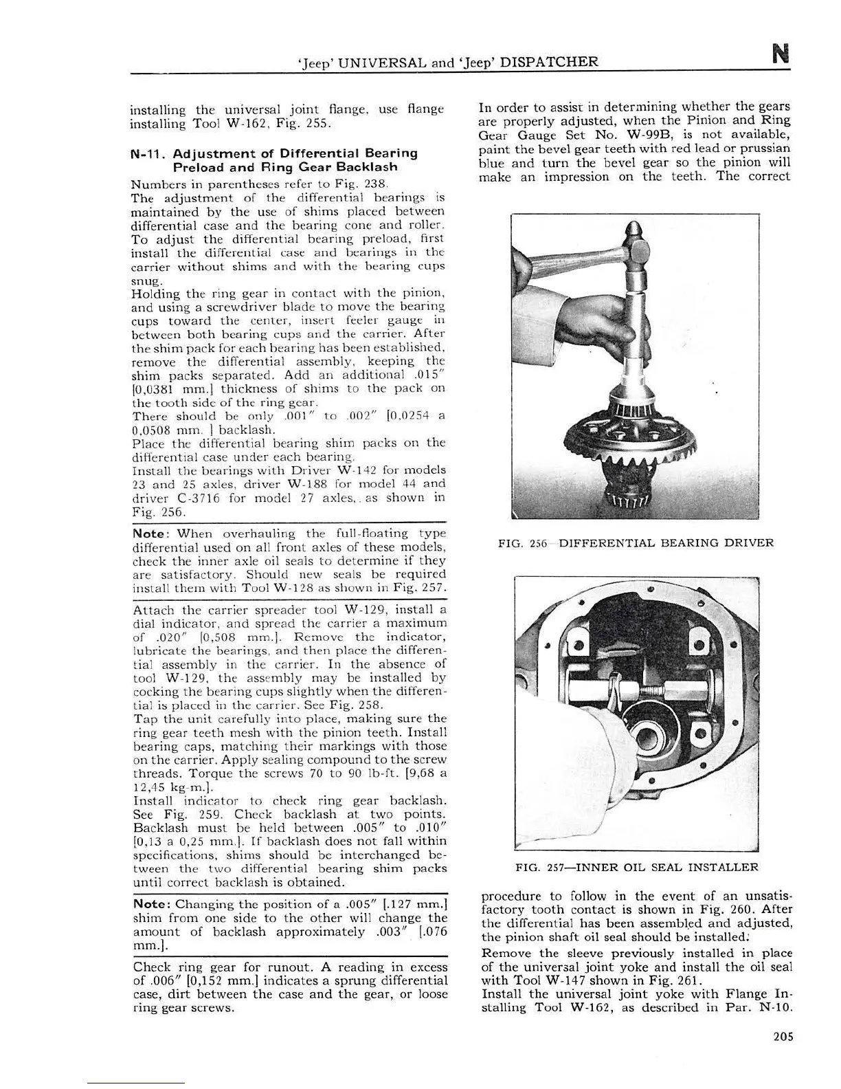
g. 256.
Note
: W
hen
ove
rh
a
ulin
g
the
fu
ll
-
float
i
ng
typ
e
differen
tia
l u
sed
on
all
front
ax
l
es
of
these
mode
ls,
check
the inn
er
axle
oil
seals
to
deter
mi
ne
if th
ey
are
sat
is
factory.
Sho
u
ld
new
sea
ls
be
re
qu
ir
ed
install
th
em
wi
th
Too
l W -128
as
shown
in
Fi
g. 257.
A
ttach
the
carr
i
er
spr
ea
der
tool
W-
129,
ins
tall
a
d i
al
indicator,
and
spread
the
car
rier a
maxim
um
of
.020"
[0,508
mm
.
].
Remove
the
in
di
cator,
lu
br
i
cate
the
bearings,
and
then
place
the
di
fferen-
tial
asse
m
bly
in
the
ca
rri
er.
In the a
bs
en
ce
of
too
l W -129.
the
ass
e
mbly
may
be
in
stalled
by
coc
ki
ng
the
bear
i
ng
cups
sli
ght
ly wh
en
the
di
fferen-
tia
l is pl
aced
in the
ca
r
rier.
See
Fig
. 258.
T
ap
the unit
ca
r
ef
ully
into
place
, making s
ur
e the
rin
g
gear
tee
th
mesh
wi
th
the
pin
ion
teet
h.
Ins
ta
ll
bear
i
ng
caps
, m
atching
the
ir
ma
rk
in
gs wi
th
those
on
the
carr
i
er
. A
pply
sea
l
ing
com
po
un
d
to
the scr
ew
threads
. Torque
the
sc
r
ews
70
to
90
lb
-f
t.
(9,68 a
12,45 kg-m.].
Ins
tall
in
dicator
to
ch
eck
r
in
g
gear
bac
k
la
sh.
S
ee
Fi
g. 259. Ch
eck
bac
klash
at
two po
ints.
B
ac
klash
mu
st
be
he
ld
b
etwee
n .0
05"
to
.
01
0"
[0
,13 a 0,25 mm.].
If
bac
k
lash
d
oes
n
ot
fall w
ithin
sp
ec
i
ficat
ion
s,
s
hi
ms
sh
ou
ld
be
in
te
rc
hang
ed
be
-
tween
the
two
different i
al
b
ea
ring
shim
p
ac
ks
un
til
co
rr
ect
bac
kla
sh
is
obta
in
ed
.
Not
e :
Ch
ang
in
g t
he
posi
tion
of
a .005"
[.
12
7
mm.]
shim fr
om
one
sid
e to t he
ot
h
er
will cha
ng
e
the
amou
nt
of
b
ac
kla
sh
approxim
ate
ly .003" [.076
mm.].
Che
ck
rin
g g
ear
for
run
o
ut.
A r
ea
din
g
in
excess
of
.0
06"
[0,1
52
mm.]
indi
cate
s a
sprun
g
di
ffe
ren
t
ial
cas
e,
dirt
bet
we
en
the
ca
se
and
the
gear,
or
loos
e
ring
gear
sc
rew
s.
In
order
to
assist
in
dete
rminin
g
wh
et
h
er
t he
gears
ar
e
prop
e
rl
y
adjust
ed,
wh
en
th
e
Pin
io
n
and
Ring
G
ea
r Gau
ge
Se
t No . W -
99B
, is n
ot
availabl
e,
p
ain
t
th
e bevel
gear
t
eeth
wi
th r
ed
lea
d
or
prussian
b
lu
e
and
t
urn
th
e
bev
el g
ea
r so t he
pini
on
will
make an
im
pre
ssion
on
t he
teeth
.
Th
e co
rrec
t
FI
G.
256
DIF
F
ERE
NTI
AL
BEA
RIN
G
DRIVER
-
--
J
F IG . 257
-INNER
OIL
SEAL
INSTALLER
pro
ce
dur
e
to
follow
in
th
e eve
nt
of an
unsatis
-
fac
t
or
y t
oo
th
co
ntact
is
shown
in
Fig.
260.
After
the
diff
ere
nti
al
has
been
assemb
l.e
d and a
djusted
,
th
e
pini
on
sh
a
ft
oil
seal
should
be
inst
alled :
Remove
the
sleeve
previousl
y
ins
t
alled
in
plac
e
of
th
e
univ
e
rsal
joint
yoke
and
install
th
e oil
seal
with
Tool
W -
14
7
shown
in
Fig
. 261 .
Inst
all
th
e
universal
joint
yoke
with
Flang
e In -
stalling
Tool
W -162 ,
as
describ
ed
in
Par.
N-10
.
205