EasyManua.ls Logo

Jeep UNIVERSAL CJ-2A - Page 205

Jeep UNIVERSAL CJ-2A
281 pages
Print Icon
To Next Page IconTo Next Page
To Previous Page IconTo Previous Page
Loading...
N
REAR
AXLE
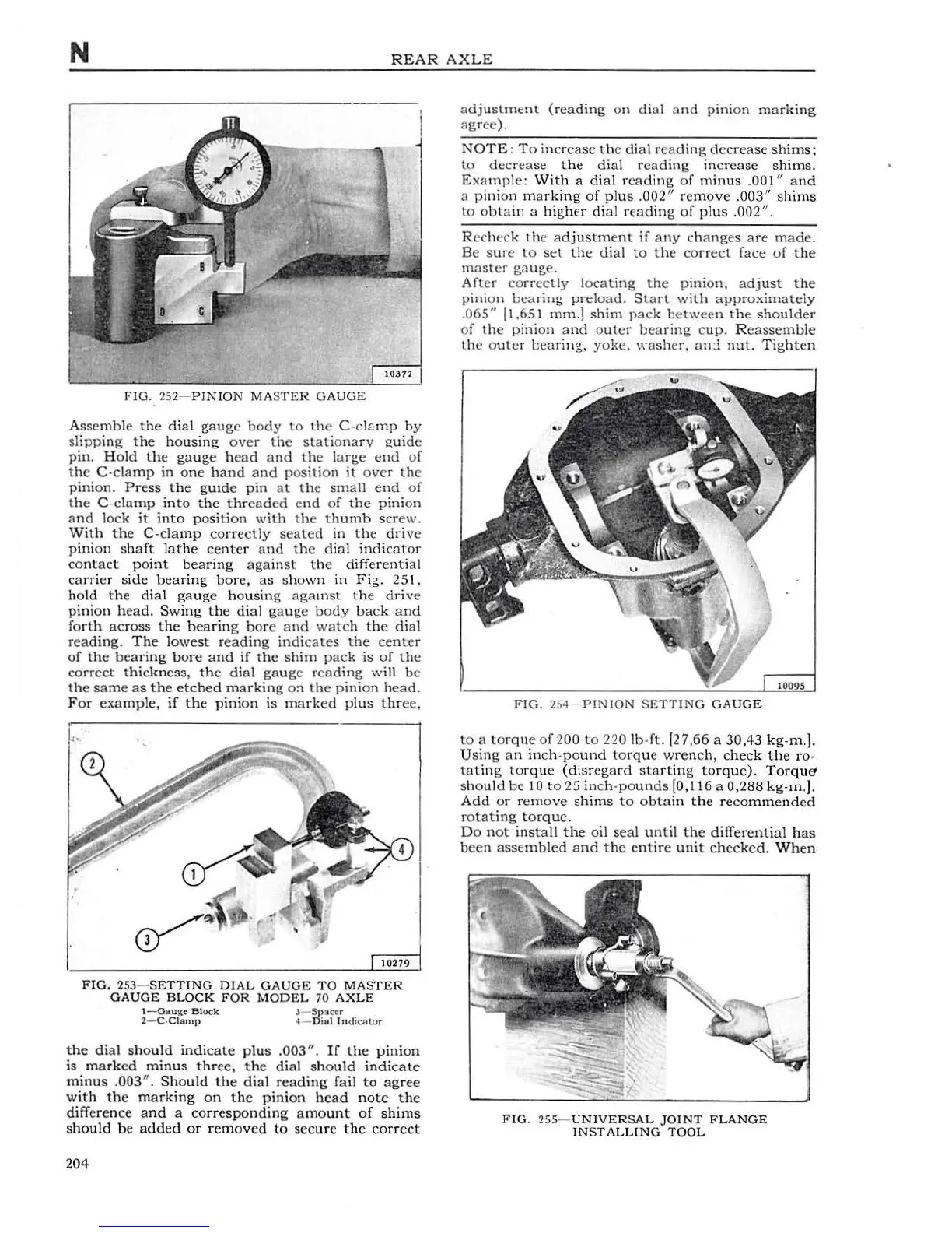
FIG.
252-
PlNION
MASTER
GAUGE
Assemble
the
dial
ga
uge
body
to
the
C-
clamp
by
slipping
the
housing
over
the
stationary
gu
i
de
pin.
H
old
the
ga
uge
head
and
the
large
end
of
the
C-cla
mp
in
one
hand
and
position
it
ove
r
the
p
in
ion.
P r
ess
t he gUJde
pin
at
the
small
end
of
the
C-cla
mp
into
t
he
threaded
e
nd
of
the
pinion
a
nd
Jock
it
into
position
with
the
thumb
screw.
Wi
th
the
C-cla
mp
co
rr
ectly
seated
in
the
d
ri
ve
pini
on
sha
ft
lathe
center
and
the
dial
indicator
co
nt
act
point
bearing
aga
in
st
the differ
ent
i
al
carrier
side
bearing
bore,
as
sh
own
in
Fig.
251.
ho
ld
t
he
dial
gaug
e
housin
g
aga
m
st
th
e
drive
pinion h
ea
d.
Swing
the
dial
ga
uge
body
back
and
forth
acros
s t
he
b
ea
rin
g
bo
re
and
watch
the
dia
l
read
in
g.
The
lowest
reading
ind
i
cates
the
center
of
the
bea
ring
bore
and
if
the
shim
pack
is
of
the
correct
thi
ckness
, the
dial
gauge
reading
will
be
the
same
as
the
etc
hed
ma
rk
ing 0
:1
the
pinion
head.
F
or
exa
mple,
if
the
pinion
is
marked
pl
us
th
r
ee,
FIG.
253-
SETTING
DIAL
GAUGE
TO
MASTER
GAUGE
BLOCK
FOR
MODEL
70
AXLE
!-
Gauge
Bl
ock
2-C·Ciamp
3-
Spscer
·1-
Diol
In
dicator
the
di
al
should
indi
cate
plus
.003".
If
the
pinion
is
marked
minus
three
, t he
dial
should
indicate
minus
.003".
Should
the
dial
reading
fail
to
agree
with
the
marking
on
the
pin
i
on
head
note
the
diff
ere
nce
and
a
corresponding
amount
of
shims
should
be
added
or
removed
to
secure
the
correct
204
adjustment
(reading
on
dial
and
pinion
ma
r
king
agree).
NOTE
:
To
increase
the
dial
r
ead
ing
dec
r
ea
se
shims;
to
decrea
se t
he
dial
r
ead
ing
increase
shims.
Examp
l
e:
With
a
dial
r
ead
in
g of
minus
.001" a
nd
a pini
on
mark
ing
of
plus
.002" re
move
.003"
sh
ims
to
obta
in
a
higher
di
al
reading
of
plus
.002
".
R
ec
ht:
ck
the
ad
jus
tment
if
any
c
hanges
are
made.
Be
sure
to
set
the
di
al
to
the
co
rrect
face
of
the
master
gauge.
Aft
er
correctly
locating
the
pinion
.
adjust
t
he
pinion
bearing
preload.
Start
with
approximately
.065''
11.651 mm.J
shim
pack
between
the
shoulder
of
the
pi
nion
and
ou
te
r
bearing
cup
. R
eassemble
th
e o
uter
beari
ng,
yoke.
washer,
an:i
nut
.
Tighten
FI
G . 254
PINION
SETT
ING
GAUGE
to
a
to
rqu
e
of200
to
220
lb
-ft. [27,66 a
30,43
kg-m.].
Us
in
g
an
inch
-po
und
torq
ue
wrench,
chec
k
the
ro-
tati
ng
torq
ue
(disr
ega
rd
starting
torque)
.
Torqu~
sho
uld
be
I 0
to
25
in
ch-
pounds
[0
, 116 a 0,
288
kg-m.].
A
dd
or
remove
shims
to
ob
ta
in
the
rec
ommended
rotating
t
or
qu
e.
Do
not
i
nsta
ll
the
oil
seal
until
the differe
ntial
has
been
assembled
and
t he
entire
unit
chec
ked.
When
FIG.
255-
UNIVERSAL
JOINT
FLANGE
INSTALLING
TOOL