EasyManua.ls Logo

Jeep UNIVERSAL CJ-2A - Page 204

Jeep UNIVERSAL CJ-2A
281 pages
Print Icon
To Next Page IconTo Next Page
To Previous Page IconTo Previous Page
Loading...
'J
eep'
UNIVERSAL
a
nd
'J
eep'
DISPATCHER
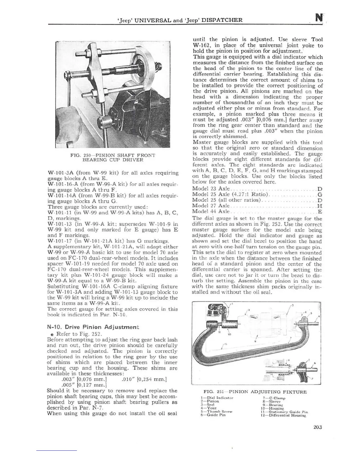
FIG.
250
PINION
SHAFT
FRONT
BEARING
CUP
DRIVER
W-
101
-
3A
(from
W -99
kit)
for all
axles
requiring
gauge
blocks
A
thru
E.
W -101-16-A
(from
W -99-A ki
t)
f
or
all
axles
requi
r-
ing
gauge
blocks
A
tbru
F.
W -
101
-14A
(fr
om
W-99-B
ki
t)
for
a!l
axles
re
quir-
ing
gauge
blocks
A
thru
G .
Thre
e
ga
ug
e
bloc
ks
are
cu
rr
ently
used
:
W -
10
1-11
(in
W-99
and
W -99-A
kits
)
ha
s A, B , C ,
D,
m
ar
kmgs
.
W -101-13
(in
W -99-A ki
t;
sup
ersedes
W-101-9
in
W -
99
kit
and
o
nly
mark
ed
for
E
gauge)
has
E
and
F
mark
in
gs.
W -101-17
(in
W -101-
21A
ki
t)
has
G
markings
.
A
suppl
ementary
ki
t,
W-101-
21
A. will
adapt
eit
h
er
W -99
or
W -
99-A
basic
kit
to
us
e for
model
70
axl
e
us
ed
on
FC-1
70
dual
-
rear
-
whee
l
models.
It
includes
spa
cer
W -
101
-19 n
eeded
for
model
70
axle
used
on
FC
-170
dual
-r
ea.
r
-whe<::l
models.
This
suppl
emen-
tary
kit
plus
W -
10
1-24
gaug
e
block
will
make
a
W -99-A
kit
equal
to
a
W-99-B
kit.
Subs
t
ituting
W -I
01
-1
6A
C-
clamp
aligning
fixture
for W -
101
-
3A
and
adding
W-10
1-13
gaug
e
block
to
the
W -99
kit
will
bring
a
W-9
9 kit
up
to
includ
e
th
e
same
items
as
a
W-99
-A ki
t.
Th
e
cor
r
ect
gauge
for
settin
g
axles
covered
in
this
book
is
indi
cated
in
Par
N-1
0.
N-10.
Driv
e
Pinion
Adjustmen
t
• R
efer
to
Fig.
252.
Before
attempt
ing
to
adjust
the
ring
gear
back
lash
and
ru
n
out,
the
drive
pinion
shoul
d
be
ca
r
efully
c
he
ck
ed
and
adjusted.
Th
e
pinion
is
correctly
positioned
in
r
elat
ion
to
the
ring
gear
by
the
us
e
of
shims
whi
ch
are
placed
between
the
inn
er
bearing
c
up
and
the
housing.
Thes
e
shims
ar
e
ava
il
able
in
t
hes
e
thicknesses:
.003" [0,076
mm.)
.010" [0,254
mm.
)
.005" [
0,127
mm.
J
Should
it
be
necessary
to
remove
and
replac
e
the
pinion
sh
aft
bearing
cups,
this
may
best
be
accom
·
plish
ed
by
using
pinion
shaf
t
bearing
pullers
as
described
in
Par.
N-
7.
Wh
en
using
this
gauge
do
not
install
the
oi
l
seal
until
the
pinion
is
adjusted.
Use
sleeve
Tool
W -162,
in
place
of
the
universal
joint
yoke
to
hold
the
pinion
in
position
for
adjustment.
This
gauge
is
equipped
with
a
dial
indicator
which
measures
the
distance
from
the
finished
surface
on
the
head
of
the
pinion
to
the
cent
er
line
of
t he
differential
carrier
bearing.
Es
tablishing
this
dis
-
tance
determines
the
co
rrect
amount
of
shi
ms
to
be
installed
to
provid
e
the
correct
positioning
of
the
drive
pinion.
All
pinions
are
mark
ed
on
the
head
with
a
dimension
indicating
th
e
pro
per
number
of
thousandths
of
an
inch
they
must
be
adjusted
either
plus
or
minus
from
standa
rd.
For
exa
mple,
a
pinion
ma
r
ked
plus
three
m
eans
it
m
ust
be
adjusted
.003" [0,076
mm.]
furth
er
aw
ay
from
the
ring
gear
center
than
standard
an
d t
he
gauge
dial
must
r
ead
plus
.003"
when
the
pinion
is co
rr
ect
ly
shimmed.
M
aster
gauge
blocks
are
supplied
with
this
t
oo
l
so
that
the
o
riginal
zero
or
standard
dimension
is
acc
ur
ately
and
eas
ily
established.
Th
e
gaug
e
blocks
provide
eight
different
standards
for
dif
-
ferent
axles.
Th
e
eig
ht
standards
are
indica
ted
withA,
B,
C.
D.
E,
F ,
G,andHmarkingss
ta
mped
on
th
e
ga
uge
blocks.
Use
onl
y
the
blo
cks
listed
below for
th
e
axles
co
ve
red
here.
M
odel
23
Ax
le
. . . . . . . . . . .
M odel 25 Axle
(4
.27
:1
R
at
i
o).
M
odel
25
(all
ot
h
er
ratios)
. . . .
M
odel
27
Ax
le
..
.......
.D
M
odel
44
Ax
le
...
.....
.G
..
........
D
..
H
. E
Th
e
dial
gauge
is s
et
to
the
master
gauge
for
the
different
axles
as
shown
in
Fig
. 252.
Use
the
correct
master
gauge
surface
for
the
mode
l
axle
being
adjusted.
H
old
the
dial
indicator
and
gauge
as
shown
and
s
et
th
e
dial
bezel
to
position
the
hand
at
zero
with
one-half
t
urn
tension
on
the
gauge
pin.
This
sets
the
dial
to
register
at
zero
when
mounted
in
th
e
axle
when
the
dis
ta
n
ce
between
the
finished
he
ad
of
a
standard
pinion
and
the
center
of
the
differe
nli
al
ca
rri
er
is
spanned.
After
setting
th
e
dial,
us
e
ca
re
not
to
j
ar
it
or
t
urn
the
bezel
to
di
s-
turb
th
e
settin
g. Ass
emble
the
pinion
in
the
case
with
the
sam
e
thickness
shim
packs
originally
in-
stalled
and
witho
ut
the
oil
seal.
FIG
. 251
PINION
ADJUSTING
FIXTURE
1-
Oint
In
dicator
2-
Pini
on
3- Seol
4- V
okc
5-
Thumb
Screw
6-
Guide
Pin
7-C·
Clnmp
8-S
lc
cvo
9-
Bcarinl!
1
0-
Housin&
11
-
Statio
n
ary
Guid
e
Pin
12-
0ifferential
Housin
g
203