EasyManua.ls Logo

Jeep UNIVERSAL CJ-2A - Page 29

Jeep UNIVERSAL CJ-2A
281 pages
Print Icon
To Next Page IconTo Next Page
To Previous Page IconTo Previous Page
Loading...
D
L4-134
ENGINE
Detailed
specifications for
the
L4-134
engine
are
given
at
the
end
of
this
section.
Torque
specifica-
tions
are
at
the
end
of
this
manual
in
Section
U.
When
adjustments
are
necessary,
refer
to
these
specifications so
that
factory
clearances
are
main-
tained.
D-3.
Engin~
Mountings
The
front
of
the
engine is
supported
by
two
rubber
insulator
mountings
attached
to
the
frame
side
rail
brackets.
The
rear
of
the
engine-transmission
assembly
is
supported
by
a
rubber
insulator
mounting
under
the
rear
of
the
transmission
on
the
frame
center
cross
member.
This
cross
member
is
bolted
to
the
frame
side
rails
so
that
it
can
be
dropped
when
removing
the
transmission
or
engine-
transmission
assembly.
The
rubber
insulators
allow
free
side
and
vertical
oscillation
to
effectively
neutralize
engine
vibration
at
the
source.
The
rubber
insulator
mountings
should
be
inspected
for
separation
and
deterioration
by
jacking
the
power
plant
away
from
the
frame,
near
the
sup-
ports.
Vibration
cannot
be
effectively
absorbed
by
28
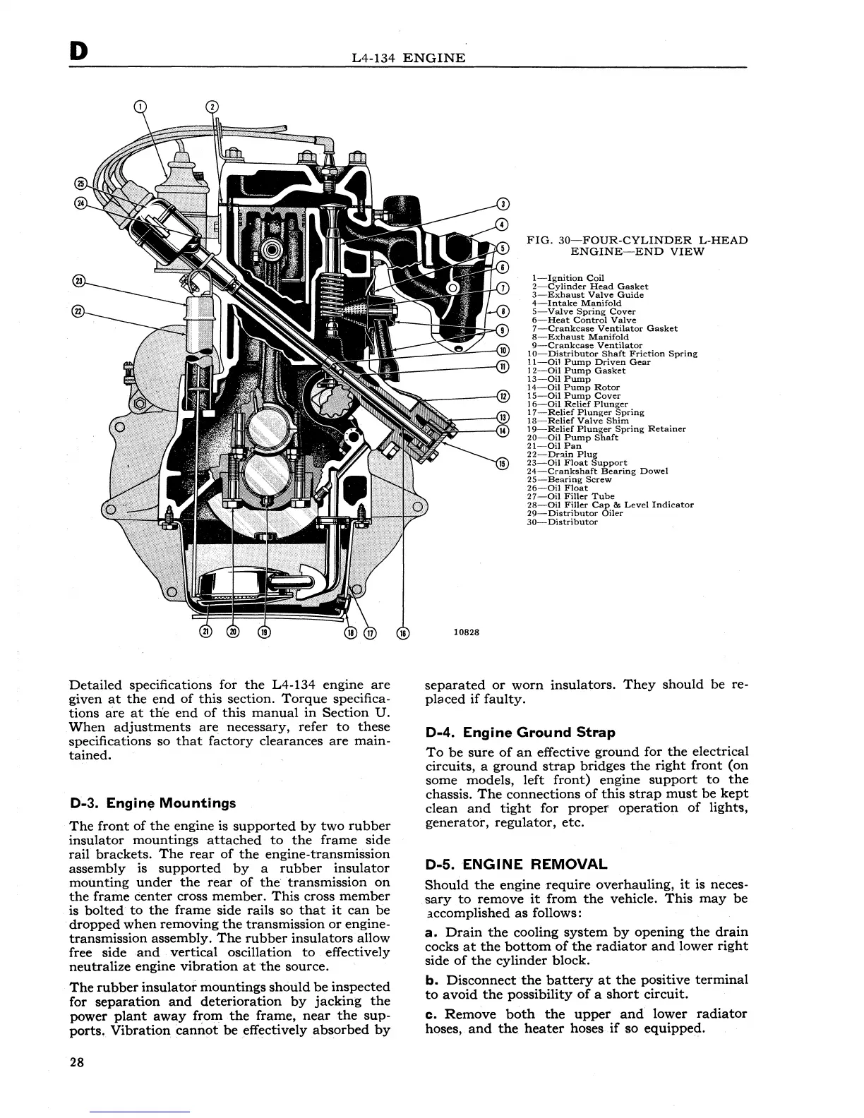
FIG.
30-FOUR-CYLINDER
L-HEAD
ENGINE-END
VIEW
!-Ignition
Coil
2-Cylinder
Head
Gasket
3-Exhaust
Valve
Guide
4-Intake
Manifold
5-Valve
Spring
Cover
6-Heat
Control
Valve
7
-Crankcase
Ventilator
Gasket
8-Exhaust
Manifold
9-Crankcase
Ventilator
1
0-
Distributor
Shaft
Friction
Spring
11-0il
Pump
Driven
Gear
1
2-0il
Pump
Gasket
13-0il
Pump
14-0il
Pump
Rotor
15-0il
Pump
Cover
16-0il
Relief
Plunger
17-Relief
Plunger
Spring
13-Relief
Valve
Shim
19-Relief
Plunger
Spring
Retainer
20-0il
Pump
Shaft
21-0il
Pan
22-Dnin
Plug
23-0il
Float
Support
24-Crankshaft.
Bearing
Dowel
25-Bearing
Screw
26-0il
Float
27-0il
Filler
Tube
28-0il
Filler
Cap
&
Level
Indicator
29-Distributor
Oiler
30-Distributor
separated
or
worn
insulators.
They
should
be
re-
placed
if
faulty.
D-4.
Engine
Ground
Strap
To
be
sure
of
an
effective
ground
for
the
electrical
circuits,
a
ground
strap
bridges
the
right
front
(on
some
models,
left
front)
engine
support
to
the
chassis.
The
connections
of
this
strap
must
be
kept
clean
and
tight
for
proper
operation
of
lights,
generator,
regulator,
etc.
D-5.
ENGINE
REMOVAL
Should
the
engine
require
overhauling,
it
is neces-
sary
to
remove
it
from
the
vehicle.
This
may
be
accomplished
as
follows:
a.
Drain
the
cooling
system
by
opening
the
drain
cocks
at
the
bottom
of
the
radiator
and
lower
right
side
of
the
cylinder
block.
b.
Disconnect
the
battery
at
the
positive
terminal
to
avoid
the
possibility
of
a
short
circuit.
c.
Remove
both
the
upper
and
lower
radiator
hoses,
and
the
heater
hoses
if
so
equipped.