EasyManua.ls Logo

Jeep UNIVERSAL CJ-2A - Page 30

Jeep UNIVERSAL CJ-2A
281 pages
Print Icon
To Next Page IconTo Next Page
To Previous Page IconTo Previous Page
Loading...
'Jeep'
UNIVERSAL
and
'Jeep'
DISPATCHER
D
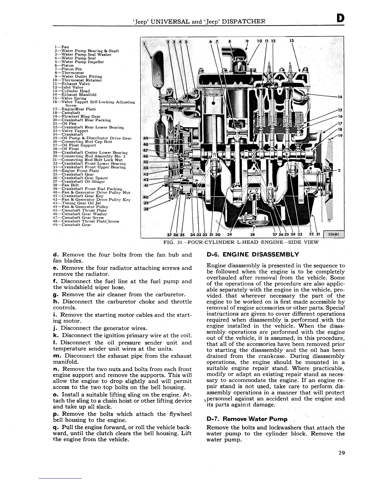
1-Fan
2-Water
Pump
Bearing
& Sh11ft
3-Water
Pump
Seal
Washer
4-Water
Pump
Seal
5-Water
Pump
Impeller
6-Piston
7-Piston
Pin
8-Thermostat
9-Water
Outlet
Fitting
10-Thermostat
Retainer
11-Exhaust
Valve
12-,--Inlet
Valve
13-Cylinder
Head
14-Exhaust
Manifold
IS-Valve
Spring
16-Valve
Tappet
Self-Locking
Adjusting
Screw
17-EngineRear
Plate
18-Camshaft
19-Flywheel
Ring
Gear
20-Crankshaft
Rear
Packing
21-0il
Pan
22-Crankshaft
Rear
Lower
Bearing
23-Valve
Tappet
24-Crankshaft
25-0il
Pump
&
Distributor
Drive
Gear
26-Connecting
Rod
Cap
Bolt
27-0il
Float
Support
28-0il
Float
29-Crankshaft
Center
Lower
Bearing
30-Connecting
Rod
Assembly
No.
2
31-Connecting
Rod
Bolt
Lock
Nut
32-Crankshaft
Front
Lowtr
Bearing
33-Crankshaft
Front"Upper
Bearing
34-Engine
Front
Plate
35-Crankshaft
Gear
36-Crankshaft
Gear
Spacer
37-Crankshaft
Oil
Slinger
38-Fan
Belt
39~Crankshaft
Front
End
Packing
40-Fan
&
Generator
Drive
Pulley
Nut
41-Crankshaft
Gear
Key
42-Fan
&
Generator
Drive
Pulley
Key
43-Timing
Gear
Oil
Jet
44-Fan
&
Generator
Pulley
45-Camshaft
Thrust
Plate
4
6-Camshaft
Gear
Washer
47-Camshaft
Gear
Screw
48-Camshaft
Thrust
PlatC:Screw
4Q-Camshaft
Gear
d.
Remove
the
four
bolts
from
the
fan
hub
and
ian
blades.
e.
Remove
the
four
radiator
attaching
screws
and
remove
the
radiator.
f.
Disconnect
the
fuel
line
at
the
fuel
pump
and
the
windshield
wiper
hose.
g.
Remove
the
air
cleaner
from
the
carburetor.
h.
Disconnect
the
carburetor
choke
and
throttle
controls.
i.
Remove
the
starting
motor
cables
and
the
start-
ing
motor.
j.
Disconnect
the
generator
wires.
k.
Disconnect
the
ignition
primary
wire
at
the
coil.
I.
Disconnect
the
oil
pressure
sender
unit
and
temperature
sender
unit
wires
at
the
units.
m.
Disconnect
the
exhaust
pipe
from
the
exhaust
manifold.
n.
Remove
the
two
nuts
and
bolts
from
each
front
engine
support
and
remove
the
supports.
This
will
allow
the
engine
to
drop
slightly
and
will
permit
access
to
the
two
top
bolts
on
the
bell
housing.
o.
Install
a
suitable
lifting
sling
on
the
engine;
At-
tach
the
sling
to
a c.hain
hoist
or
other
lifting
device
and
take
up
all
slack.
p.
Remove
the
bolts·
which
attach
the
·flywheel
bell
housing
to
the
engine. ·
q.
Pull
the
engine
forward,
or
roll
the
vehicle
back-
ward,
until
the
clutch
cleats
the
bell
housing.
Lift
the
engine
from
the
vehicle. · ·
D-6.
ENGINE
DISASSEMBLY
Engine
disassembly
is
presented
in
the
sequence
to
be
followed
when
the
engine
is
to
be
completely
overhauled
after
removal
from
the
vehicle.
Some
of
the
operations
of
the
procedure
are
also applic-
able
separately
with
the
engine
in
the
vehicle, pro-
vided
that
wherever
necessary
the
part
of
the
engine
to
be
worked
on
is first
made
accessible
by
removal
of
engine
accessories
or
other
parts.
Special
instructions
are
given
t<>
cover
different
operations
required
when
disassembly
is
performed
with
the
engine
installed
in
the
vehicle.
When
the
disas-
sembly
operations
are
performed
with
the
engine
out
of
the
vehicle,
it
is
assumed,
in
this
procedure,
that
all
of
the
accessories
have
been
removed
prior
to
starting
the
disassembly
and
the
oil
has
been
drained
from
the
crankcase.
During
disassembly
operations,
the
engine
should
be
mounted
in
a
suitable
engine
repair
stand.
Where
practicable,
modify
or
adapt
an
existing
repair
staQd
as
neces-
sary
to
accommodate
the
engine:
If
an
engine re-
pair
stand
is
not
used,
take
care
to
perform
dis-
assembly
operations
in
,a
manner
that
will
protect
~personnel
against
an
accident
and
the
engine
and
its
parts
agaimt
damage.
D-7. Remove
Wa~~r
Pump
Remove
the
bolts
and
lockwashers
that
attach
the
water
pump
to
the
cylinder
block.
Remove
the
water
pump.
··