EasyManua.ls Logo

Jeep UNIVERSAL CJ-2A - Page 36

Jeep UNIVERSAL CJ-2A
281 pages
Print Icon
To Next Page IconTo Next Page
To Previous Page IconTo Previous Page
Loading...
'Jeep'
UNIVERSAL
and
'Jeep'
DISPATCHER
D
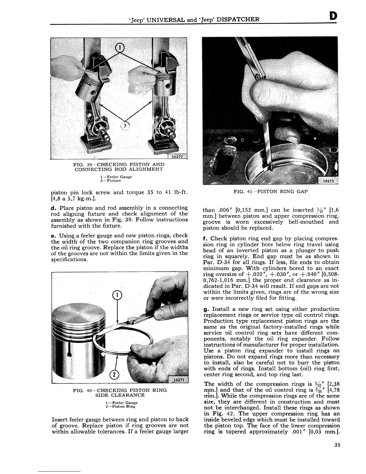
FIG.
39ยท-CHECKING
PISTON
AND
CONNECTING
ROD
ALIGNMENT
1-Feeler
Gauge
2-Fixture
piston
pin
lock
screw
and
torque
35
to
41
lb-ft.
[4,8 a 5,7 kg-m.].
d.
Place
piston
and
rod
assembly
in
a
connecting
rod
aligning
fixture
and
check
alignment
of
the
assembly
as
shown
in
Fig.
39.
Follow
instructions
furnished
with
the
fixture.
e.
Using
a feeler
gauge
and
new
piston
rings,
check
the
width
of
the
two
companion
ring
grooves
and
the
oil
ring
groove.
Replace
the
piston
if
the
widths
of
the
grooves
are
not
within
the
limits
given
in
the
specifications.
FIG.
40-CHECKING
PISTON
RING
SIDE
CLEARANCE
1-Feeler
Gauge
2-Piston
Ring
Insert
feeler
gauge
between
ring
and
piston
to
back
of
groove.
Replace
piston
if
ring
grooves
are
not
within
allowable
tolerances.
If
a feeler
gauge
larger
FIG.
41--PISTON
RING
GAP
than
.006"
[0,152 mm.]
can
be
inserted
hi;" [1,6
mm.]
between
piston
and
upper
compression ring,
groove
is
worn
excessively
bell-mouthed
and
piston
should
be
replaced.
f.
Check
piston
ring
end
gap
by
placing
compres-
sion
ring
in
cylinder
bore
below
ring
travel
using
head
of
an
inverted
piston
as
a
plunger
to
push
ring
in
squarely.
End
gap
must
be
as
shown
in
Par.
D-34
for
all
rings.
If
less, file
ends
to
obtain
minimum
gap.
With
cylinders
bored
to
an
exact
ring
oversize
of
+.020",
+.030",
or
+.040"
[0,508-
0,762-1,016 mm.]
the
proper
end
clearance
as
in-
dicated
in
Par.
D-34
will
result.
If
end
gaps
are
not
within
the
limits
given,
rings
are
of
the
wrong
size
or
were
incorrectly
filed for fitting.
g.
Install
a
new
ring
set
using
either
production
replacement
rings
or
service
type
oil
control
rings.
Production
type
replacement
piston
rings
are
the
same
as
the
original
factory-installed
rings
while
service oil
control
ring
sets
have
different
com-
ponents,
notably
the
oil
ring
expander.
Follow
instructions
of
manufacturer
for
proper
installation.
Use
a
piston
ring
expander
to
install
rings
on
pistons.
Do
not
expand
rings
more
than
necessary
to
install,
alsq
be
careful
not
to
burr
the
piston
with
ends
of
rings.
Install
bottom
(oil)
ring
first,
center
ring
second,
and
top
ring
last.
The
width
of
the
compression
rings
is
%2"
-[2,38
II}m.]
and
that
of
the
oil
control
ring
is
%"
[4,78
nim.].
While
the
compression
rings
are
of
the
same
size,
they
are
different
in
construction
and
must
not
be
interchanged.
Install
these
rings
as
shown
in
Fig.
42.
The
upper
compression
ring
has
an
inside
beveled
edge
which
must
be
installed
toward
the
piston
top.
The
face
of
the
lower compression
ring
is
tapered
approximately
.001" [0,03 mni.].
35