EasyManua.ls Logo

Jeep UNIVERSAL CJ-2A - Page 37

Jeep UNIVERSAL CJ-2A
281 pages
Print Icon
To Next Page IconTo Next Page
To Previous Page IconTo Previous Page
Loading...
D
L4-134
ENGINE
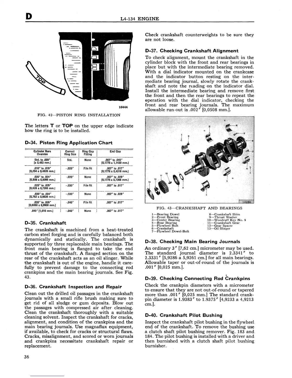
10444
FIG.
42-PISTON
RING
INSTALLATION
The
letters
T
or
TOP
on
the
upper
edge
indicate
how
the
ring
is
to
be
installed.
D-34.
Piston
Ring
Application
Chart
Cylinder Bore
Correct
Ring
Gap
End
Gap
Oversize
Ring
Size Fitting
Std. to
.009
Std.
None
.007'
to
.045'
[a
0.483
mm.)
[0,1778 a 1,1430
mm.J
.010'10
.019'
-.020'
File fit
.007'
to
.017'
[0,254 a
p,4826
mm.J
[0,1778 a 0,4318
mm.J
.020'
to .024'
-.020'
None
.007'
to
.029
[0,508
a
0,6096
mm.J
[0,1778 a 0,7366
mm.)
.025'
to
.029'
-.030'
File fit
.007'
to
.017'
[0,635 a
0,7366
mm.J
.030
to
.034
-.030'
None .007 to
.029'
[0,762 a
0,8636
mm.J
----
.035
to
.039
-.040'
File fit
.oo1·
to.o17'
[0,8890 a
0,9906
mm.J
.040'
[1,016
mm.J
-.040'
None
.007'
to
.017"
D-35.
Crankshaft
The
crankshaft
is
machined
from
a
heat-treated
carbon
steel
forging
and
is
carefully
balanced
both
dynamically
and
statically.
The
crankshaft
is
supported
by
three
replaceable
main
bearings.
The
front
main
bearing
is
flanged
to
take
the
end
thrust
of
the
crankshaft.
A
flanged
section
on
the
rear
of
the
crankshaft
acts
as
an
oil
slinger.
While
the
crankshaft
is
out
of
the
engine,
handle
it
care-
fully
to
prevent
damage
to
the
connecting
rod
crankpins
and
the
main
bearing
journals.
See
Fig.
43.
D-36.
Crankshaft
Inspection
and
Repair
Clean
out
the
drilled
oil
passages
in
the
crankshaft
journals
with
a
small
rifle
brush
making
sure
to
get
rid
of
all
sludge
or
gum
deposits.
Blow
out
the
passages
with
compressed
air
after
cleaning.
Clean
the
crankshaft
thoroughly
with
a
suitable
cleaning
solvent.
Inspect
the
crankshaft
for
cracks,
alignment,
and
condition
of
the
crankpins
and
the
main
bearing
journals.
Use
magnaflux
equipment,
if
available,
to
check
for
cracks
or
structural
flaws.
Cracks,
misalignment,
and
scored
or
worn
journals
and
crankpins
necessitate
crankshaft
repair
or
replacement.
36
Check
crankshaft
counterweights
to
be
sure
they
are
not
loose.
D-37.
Checking
Crankshaft
Alignment
To
check
alignment,
mount
the
crankshaft
in
the
cylinder
block
with
the
front
and
rear
bearings
in
place
but
with
the
intermediate
bearing
removed.
With
a
dial
indicator
mounted
on
the
crankcase
and
the
indicator
button
resting
on
the
inter-
mediate
bearing
journal,
slowly
rotate
the
crank-
shaft
and
note
the
reading
on
the
indicator
dial.
Install
the
intermediate
bearing
and
remove
first
the
front
and
then
the
rear
bearings
to
repeat
the
0peration
with
the
dial
indicator,
checking
the
front
and
rear
bearing
journals.
The
maximum
allowable
run-out
is .002
11
[0,0508
mm.].
,
\I
FIG.
43-CRANKSHAFT
AND
BEARINGS
!-Bearing
Dowel
2-Front
Bearing
3-Center
Bearing
4-Rear
Bearing
5-Flywheel
Bolt
6-Crankshaft
7-Flywheel
Dowel-Bolt
8-Crankshaft
Shim
9-Thrust
Washer
10-Woodruff
Key
No.
9
11-Crankshaft
Gear
12-Gear
Spacer
13-0il
Slinger
D-38.
Checking
Main
Bearing
Journals
An
ordinary
3
11
[7,62 em.]
micrometer
may
be
used.
The
standard
journal
diameter
is 2.3341
11
to
2.3331
11
[5,9286 a 5,9261 em.]
for
all
main
bearings.
Allowable
taper
or
out-of-round
of
the
journals
is
.001
11
[0,025
mm.].
.
D-39.
Checking
Connecting
Rod
Crankpins
Check
the
crankpin
diameters
with
a
micrometer
to
ensure
that
they
are
not
out-of-round
or
tapered
more
than
.001
11
[0,025
mm.]
The
standard
crank-
pin
diameter
is 1.9383
11
to
1.9375
11
[4,9233 a 4,9213
em.].
D-40.
Crankshaft
Pilot
Bushing
Inspect
the
crankshaft
pilot
bushing
in
the
flywheel
end
of
the
crankshaft.
To
remove
the
bushing
use
a
clutch
shaft
pilot
bushing
remover.
Fig.
183
and
184.
The
pilot
bushing
is
installed
with
a
driver
and
then
burnished
with
a
clutch
shaft
pilot
bushing
burnisher.