EasyManua.ls Logo

Jeep UNIVERSAL CJ-2A - Page 43

Jeep UNIVERSAL CJ-2A
281 pages
Print Icon
To Next Page IconTo Next Page
To Previous Page IconTo Previous Page
Loading...
D
L4-134
ENGINE
D-60.
Crankshaft
Rear Bearing
Seal
Oil
leakage
through
the
rear
main
bearing
is
pre-
vented
by
a
metal
supported
neoprene
lip
type
seal
which
can
readily
be
installed
without
remov-
ing
the
crankshaft.
Should
trouble
be
experienced
with
oil
leaking
from
the
rear
main
bearing
there
are
several
points
which
should
be
checked.
a.
Be
sure
that
the
identifying
paint
daub
on
the
bearing
cap
is
the
same
as
that
appearing
on
the
center
bearing
web.
b.
The
bearing
to
crankshaft
clearance
must
not
exceed .0029" [0,0736].
c.
Place
sealer
on
the
faces
of
the
rear
bearing
cap
from
the
rear
oil groove
to
the
oil seal grooves.
d.
Be
sure
the
rubber
oil seals
extend
about
.74:"
[6
mm.] below
the
bottom
face
of
the
cap.
e.
Be
sure
the
oil
pan
gasket
is
not
leaking.
f.
Check
to
be
sure
the
oil
leak
is
not
at
the
cam-
shaft
rear
bearing
expansion
plug
or
from
the
crankcase.
D-61.
Floating
Oil
Intake
The
floating oil
intake
is
attached
to
the
bottom
of
the
crankcase
with
two
screws.
The
float
and
screen
causes
it
to
ride, raise
and
lower
with
the
amount
of
oil
in
the
pan.
This
prevents
water
or
dirt,
which
may
have
accumulated
in
the
bottom
of
the
oil
pan,
from
circulating
through
the
engine
because
the
oil is
drawn
horizontally
from
the
top
surface.
Whenever
removed,
the
float, screen,
and
tube
should
be
cleaned
thoroughly
to
remove
any
accumulation
of
dirt.
Also
clean
the
oil
pan.
Fluctuating
oil
pressure
can
usually
be
traced
to
an
air
leak
between
the
oil float
support
and
the
crankcase.
Be
sure
the
float
support
flange is flat.
Clean
both
the
flange
and
the
crankcase
surfaces
thoroughly
before
installing
a
new
gasket.
Be
sure
the
retaining
screws
are
tight.
42
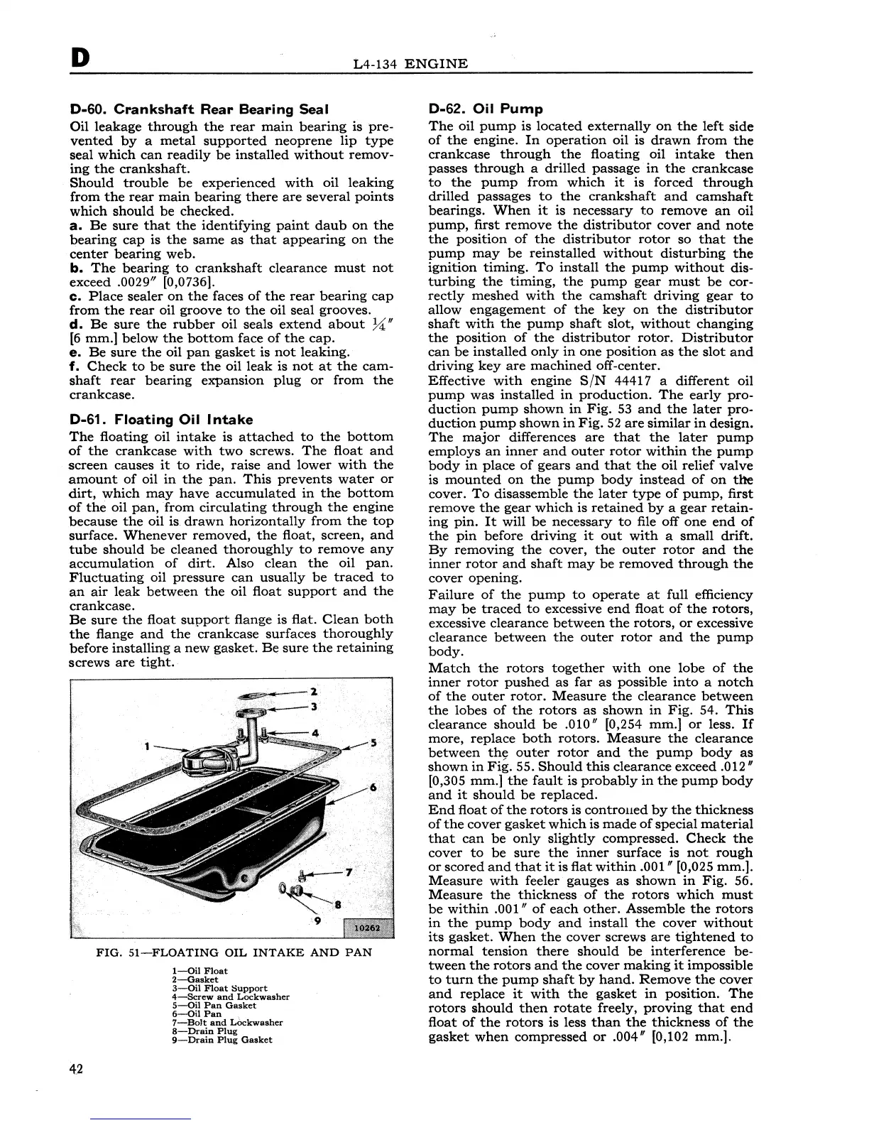
FIG.
51-FLOATING
OIL
INTAKE
AND
PAN
1-0il
Float
2-Gasket
3-0il
Float
Support
4-Sc:rew
and
Lockwasher
5-Qil
Pan
Gasket
6-0il
Pan
.
7-Bolt
and
Lockwasher
8-Drain
Plug
9-Drain
Plug
Gasket
D-62. Oil
Pump
The
oil
pump
is
located
externally
on
the
left
side
of
the
engine.
In
operation
oil is
drawn
from
the
crankcase
through
the
floating
oil
intake
then
passes
through
a drilled
passage
in
the
crankcase
to
the
pump
from
which
it
is
forced
through
drilled
passages
to
the
crankshaft
and
camshaft
bearings.
When
it
is
necessary
to
remove
an
oil
pump,
first
remove
the
distributor
cover
and
note
the
position
of
the
distributor
rotor
so
that
the
pump
may
be
reinstalled
without
disturbing
the
ignition
timing.
To
install
the
pump
without
dis-
turbing
the
timing,
the
pump
gear
must
be
cor-
rectly
meshed
with
the
camshaft
driving
gear
to
allow
engagement
of
the
key
on
the
distributor
shaft
with
the
pump
shaft
slot,
without
changing
the
position
of
the
distributor
rotor.
Distributor
can
be
installed
only
in
one
position
as
the
slot
and
driving
key
are
machined
off-center.
Effective
with
engine
S/N
44417 a different oil
pump
was
installed
in
production.
The
early
pro-
duction
pump
shown
in
Fig.
53
and
the
later
pro-
duction
pump
shown
in
Fig.
52
are
similar
in
design.
The
major
differences
are
that
the
later
pump
employs
an
inner
and
outer
rotor
within
the
pump
body
in
place
of
gears
and
that
the
oil relief
valve
is
mounted
on
the
pump
body
instead
of
on
the
cover.
To
disassemble
the
later
type
of
pump,
first
remove
the
gear
which
is
retained
by
a
gear
retain-
ing
pin.
It
will
be
necessary
to
file
off
one
end
of
the
pin
before
driving
it
out
with
a
small
drift.
By
removing
the
cover,
the
outer
rotor
and
the
inner
rotor
and
shaft
may
be
removed
through
the
cover
opening.
Failure
of
the
pump
to
operate
at
full efficiency
may
be
traced
to
excessive
end
float
of
the
rotors,
excessive
clearance
between
the
rotors,
or
excessive
clearance
between
the
outer
rotor
and
the
pump
body.
Match
the
rotors
together
with
one
lobe
of
the
inner
rotor
pushed
as
far
as
possible
into
a
notch
of
the
outer
rotor.
Measure
the
clearance
between
the
lobes
of
the
rotors
as
shown
in
Fig.
54.
This
clearance
should
be
.010" [0,254 mm.]
or
less.
If
more, replace
both
rotors.
Measure
the
clearance
between
th~
outer
rotor
and
the
pump
body
as
shown
in
Fig.
55.
Should
this
clearance exceed .012"
[0,305
mm.]
the
fault
is
probably
in
the
pump
body
and
it
should
be
replaced.
End
float
of
the
rotors
is
controued
by
the
thickness
of
the
cover
gasket
which
is
made
of
special
material
that
can
be
only
slightly
compressed.
Check
the
cover
to
be
sure
the
inner
surface
is
not
rough
or
scored
and
that
it
is
flat
within
.001" [0,025 mm.].
Measure
with
feeler gauges
as
shown
in
Fig.
56.
Measure
the
thickness
of
the
rotors
which
must
be
within
.001"
of
each
other.
Assemble
the
rotors
in
the
pump
body
and
install
the
cover
without
its
gasket.
When
the
cover
screws
are
tightened
to
normal
tension
there
should
be
interference
be-
tween
the
rotors
and
the
cover
making
it
impossible
to
turn
the
pump
shaft
by
hand.
Remove
the
cover
and
replace
it
with
the
gasket
in
position.
The
rotors
should
then
rotate
freely,
proving
that
end
float
of
the
rotors
is less
than
the
thickness
of
the
gasket
when
compressed
or
.004" [0,102 mm.].