EasyManua.ls Logo

Jeep UNIVERSAL CJ-2A - Page 48

Jeep UNIVERSAL CJ-2A
281 pages
Print Icon
To Next Page IconTo Next Page
To Previous Page IconTo Previous Page
Loading...
'Jeep'
UNIVERSAL
and
'Jeep'
DISPATCHER
D
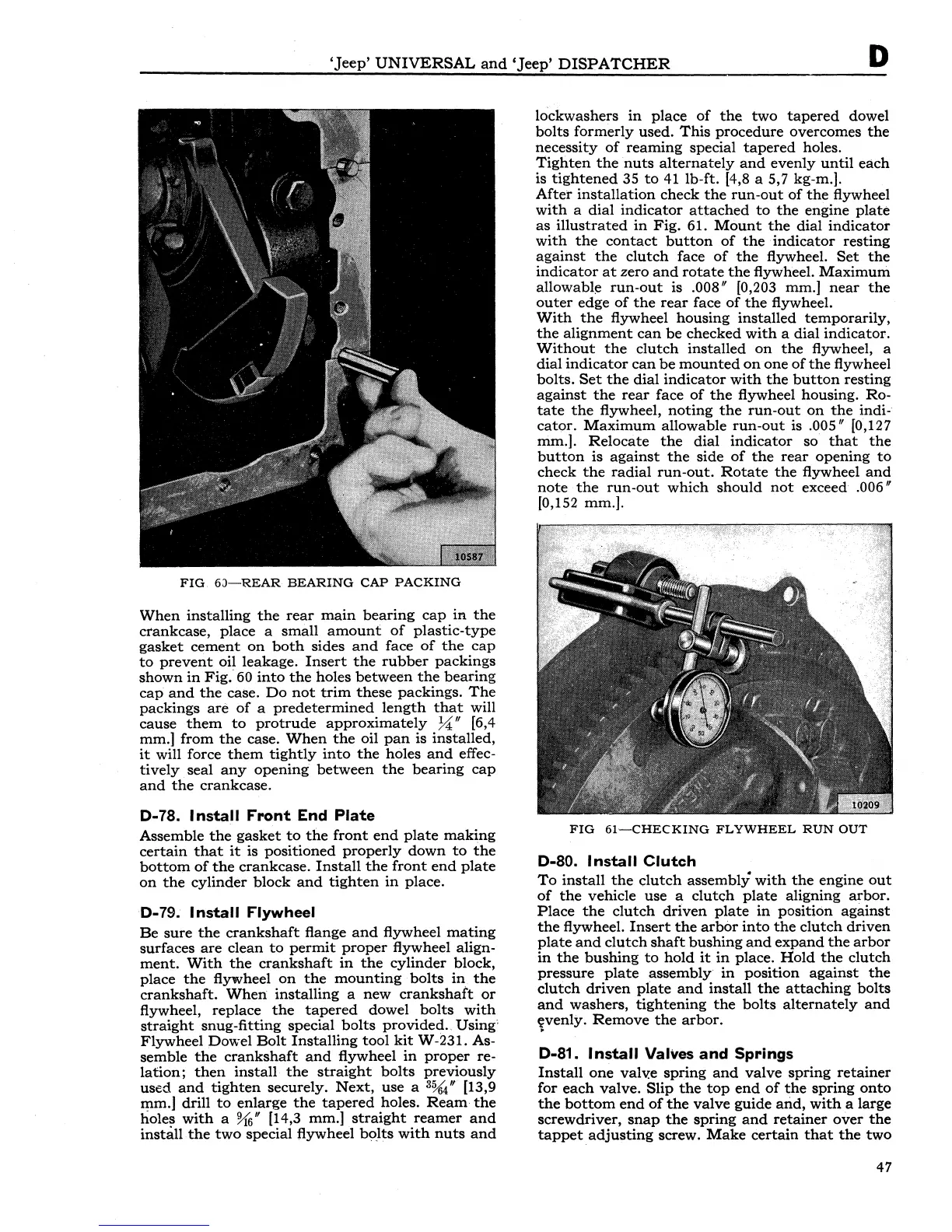
FIG.
6J-REAR
BEARING
CAP
PACKING
When
installing
the
rear
main
bearing
cap
in
the
crankcase,
place
a
small
amount
of
plastic-type
gasket
cement
on
both
sides
and
face
of
the
cap
to
prevent
oil
leakage.
Insert
the
rubber
packings
shown
in
Fig.
60
into
the
holes
between
the
bearing
cap
and
the
case.
Do
not
trim
these
packings.
The
packings
are
of
a
predetermined
length
that
will
cause
them
to
protrude
approximately
~"
[6,4
mm.]
from
the
case.
When
the
oil
pan
is
installed,
it
will force
them
tightly
into
the
holes
and
effec-
tively
seal
any
opening
between
the
bearing
cap
and
the
crankcase.
D-78.
Install
Front
End
Plate
Assemble
the
gasket
to
the
front
end
plate
making
certain
that
it
is
positioned
properly
down
to
the
bottom
of
the
crankcase.
Install
the
front
end
plate
on
the
cylinder
block
and
tighten
in
place.
D-79.
Install
Flywheel
Be
sure
the
crankshaft
flange
and
flywheel
mating
surfaces
are
clean
to
permit
proper
flywheel
align-
ment.
With
the
crankshaft
in
the
cylinder
block,
place
the
flywheel
on
the
mounting
bolts
in
the
crankshaft.
When
installing
a
new
crankshaft
or
flywheel,
replace
the
tapered
dowel
bolts
with
straight
snug-fitting
special
bolts
provided.
Using·
Flywheel
Dowel
Bolt
Installing
tool
kit
W-231. As-
semble
the
crankshaft
and
flywheel
in
proper
re-
lation;
then
install
the
straight
bolts
previously
used
and
tighten
securely.
Next,
use
a
3%4"
[13,9
mm.J drill
to
enlarge
the
tapered
holes.
Ream
the
holes
with
a %;" [14,3 mm.]
straight
reamer
and
instaJl
the
two
special flywheel
bolts
with
nuts
and
lockwashers
in
place
of
the
two
tapered
dowel
bolts
formerly
used.
This
procedure
overcomes
the
necessity
of
reaming
special
tapered
holes.
Tighten
the
nuts
alternately
and
evenly
until
each
is
tightened
35
to
41 lb-ft. [4,8 a 5,7 kg-m.].
After
installation
check
the
run-out
of
the
flywheel
with
a
dial
indicator
attached
to
the
engine
plate
as
illustrated
in
Fig.
61.
Mount
the
dial
indicator
with
the
contact
button
of
the
indicator
resting
against
the
clutch
face
of
the
flywheel.
Set
the
indicator
at
zero
and
rotate
the
flywheel.
Maximum
allowable
run-out
is .008" [0,203 mm.]
near
the
outer
edge
of
the
rear
face
of
the
flywheel.
With
the
flywheel
housing
installed
temporarily,
the
alignment
can
be
checked
with
a
dial
indicator.
Without
the
clutch
installed
on
the
flywheel, a
dial
indicator
can
be
mounted
on
one
of
the
flywheel
bolts.
Set
the
dial
indicator
with
the
button
resting
against
the
rear
face
of
the
flywheel housing.
Ro-
tate
the
flywheel,
noting
the
run-out
on
the
indi-
cator.
Maximum
allowable
run-out
is .005" [0,127
mm.].
Relocate
the
dial
indicator
so
that
the
button
is
against
the
side
of
the
rear
opening
to
check
the
radial
run-out.
Rotate
the
flywheel
and
note
the
run-out
which
should
not
exceed .006"
(0,152 mm.].
FIG
61-CHECKING
FLYWHEEL
RUN
OUT
D-80.
Install
Clutch
To
install
the
clutch
assembly
with
the
engine
out
of
the
vehicle
use
a
clutch
plate
aligning
arbor.
Place
the
clutch
driven
plate
in
position
against
the
flywheel.
Insert
the
arbor
into
the
clutch
driven
plate
and
clutch
shaft
bushing
and
expand
the
arbor
in
the
bushing
to
hold
it
in
place.
Hold
the
clutch
pressure
plate
assembly
in
position
against
the
clutch
driven
plate
and
install
the
attaching
bolts
and
washers,
tightening
the
bolts
alternately
and
lvenly.
Remove
the
arbor.
D-81.
Install
Valves
and
Springs
Install
one
valv:e
spring
and
valve
spring
retainer
for
each
valve.
Slip
the
top
end
of
the
spring
onto
the
bottom
end
of
the
valve
guide
and,
with
a
large
screwdriver,
snap
the
spring
and
retainer
over
the
tappet
adjusting
screw.
Make
certain
that
the
two
47