EasyManua.ls Logo

Jeep UNIVERSAL CJ-2A - Page 49

Jeep UNIVERSAL CJ-2A
281 pages
Print Icon
To Next Page IconTo Next Page
To Previous Page IconTo Previous Page
Loading...
D
L4-134
ENGINE
closely
wound
coils
of
each
spring
are
at
the
top
(placed
up
to
seat
against
the
block).
See
Fig.
62.
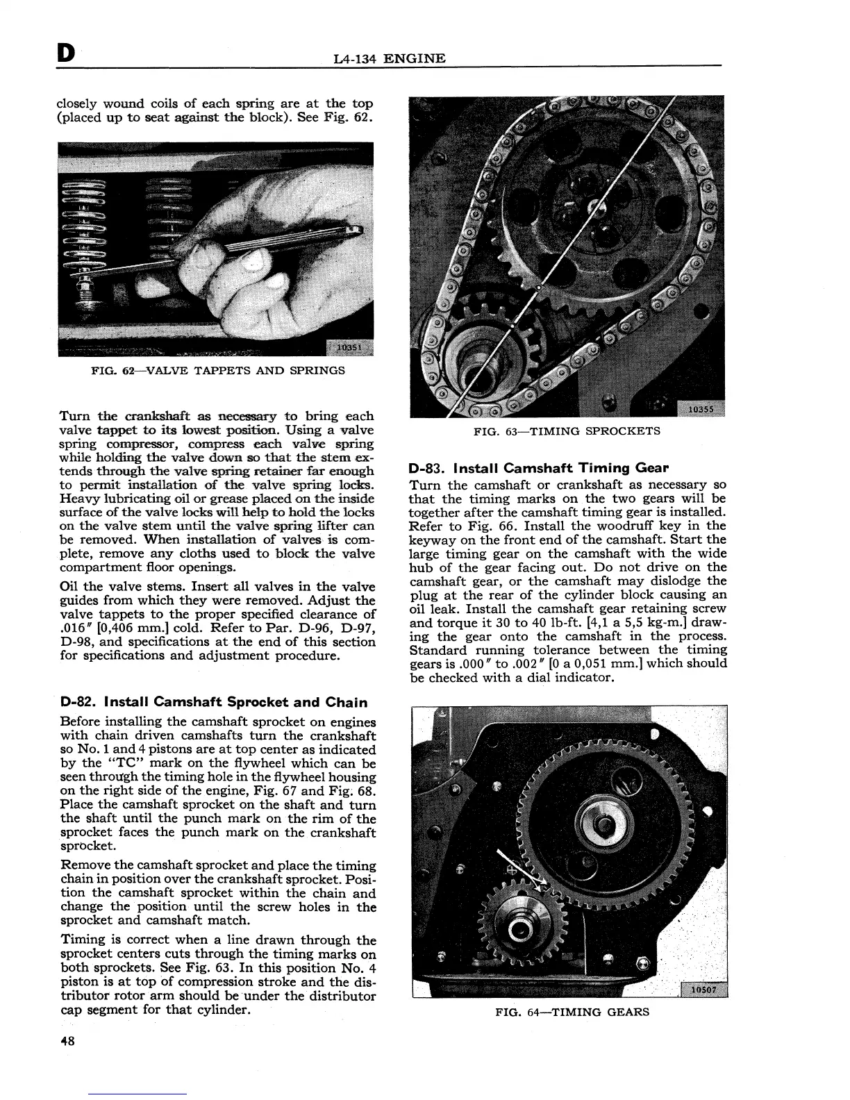
FlG.
62-VALVE
TAPPETS
AND
SPRINGS
Turn
the
crankshaft
as
necessary
to
bring
each
valve
tappet
to
its
lowest
position.
Using
a
valve
spring
compressor,
compress
each
valve
spring
while
holding
the
valve
down
so
that
the
stem
ex-
tends
through
the
valve
spring
retainer
far
enough
to
permit
installation
of
the.
valve
spring
locks.
Heavy
lubricating
oil
or
grease
plaood
on
the
inside
surface
of
the
valve
locks
will
help
to
hold
the
locks
on
the
valve
stem
until
the
valve
spring
lifter
can
be
removed.
When
installation
of
valves
is
com-
plete,
remove
any
cloths
used
to
block
the
valve
compartment
floor
openings.
Oil
the
valve
stems.
Insert
all
valves
in
the
valve
guides
from
which
they
were
removed.
Adjust
the
valve
.
tappets
to
the
proper
specified
clearance
of
.016"
[0,406
mm.]
cold.
Refer
to
Par.
D-96,
D-97,
D-98,
and
specifications
at
the
end
of
this
section
for
specifications
and
adjustment
procedure.
D-82. Install
Camshaft
Sprocket
and
Chain
Before
installing
the
camshaft
sprocket
on
engines
with
chain
driven
camshafts
turn
the
crankshaft
so
No.1
and
4
pistons
are
at
top
center
as
indicated
by
the
"TC"
mark
on
the
flywheel
which
can
be
seen
through
the
timing
hole
in
the
flywheel
housing
on
the
right
side
of
the
engine,
Fig.
67
and
Fig;
68.
Place
the
camshaft
sprocket
on
the
shaft
and
tum
the
shaft
until
the
punch
mark
on
the
rim
of
the
sprocket
faces
the
punch
mark
on
the
crankshaft
sprocket.
Remove
the
camshaft
sprocket
and
place
the
timing
chain
in
position
over
the
crankshaft
sprocket.
Posi-
tion
the
camshaft
sprocket
within
the
chain
and
change
the
position
until
the
screw
holes
in
the
sprocket
and
camshaft
match.
Timing
is
correct
when
a
line
drawn
through
the
sprocket
centers
cuts
through
the
timing
marks
on
both
sprockets.
See
Fig.
63.
In
this
position
No.
4
piston
is
at
top
of
compression
stroke
and
the
dis-
tributor
rotor
arm
should
be
Ā·under
the
distributor
cap
segment
for
that
cylinder.
48
FIG.
63-TIMING
SPROCKETS
D-83. Install
Camshaft
Timing
Gear
Turn
the
camshaft
or
crankshaft
as
necessary
so
that
the
timing
marks
on
the
two
gears
will
be
together
after
the
camshaft
timing
gear
is
installed.
Refer
to
Fig.
66.
Install
the
woodruff
key
in
the
keyway
on
the
front
end
of
the
camshaft.
Start
the
large
timing
gear
on
the
camshaft
with
the
wide
hub
of
the
gear
facing
out.
Do
not
drive
on
the
camshaft
gear,
or
the
camshaft
may
dislodge
the
plug
at
the
rear
of
the
cylinder
block
causing
an
oil
leak.
Install
the
camshaft
gear
retaining
screw
and
torque
it
30
to
40
lb-ft.
[4,1 a 5,5
kg-m.]
draw-
ing
the
gear
onto
the
camshaft
in
the
process.
Standard
running
tolerance
between
the
timing
gears
is
.000"
to
.002
11
[0
a 0,051
mm.]
which
should
be
checked
with
a
dial
indicator.
FIG.
64-TIMING
GEARS