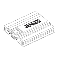
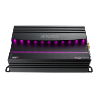
JENSEN
JA
SERIES
Connection
Descriptions
NOTE:
Be
sure
to
follow
specific
instructions
included
with
your
amplifier
installation
kit
(not
included
with
this
amplifier).
The
information
below
should
be
used
as
a
general
guideline
only.
Power
Wire
(+
12V)
• Disconnect negative battery terminal before proceeding. Consult a qualified
technician
for
instructions
if
you are unsure.
• Plan wire routing before cutting any wires to length. Begin by routing the power
+
12V
wire from the battery to the amplifier location. Use a grommet when running
wires through the firewall
or
metal openings. Avoid running the power wire near
existing vehicle wiring to prevent induced noise from entering the audio system.
• Use extreme caution when drilling holes to avoid damaging fuel lines
or
existing
vehicle wiring.
•
The
+
12V
wire
MUST
be
fused within
18"
of the battery
for
protection of the vehicle's
electrical system.
Ground
Wire
(GND)
• The amplifier ground wire should
be
as short as possible (no more than
36"
or
1 meter). Choose a clean unpainted section of metal
or
the vehicle chassis when
attaching the ground connection.
Be
sure to clean the area of any dirt
or
grease.
Remote
Tum-on
Wire
(REM)
• The remote turn-on wire connects to the head unit's amplifier turn-on lead
or
power antenna output.
Speaker
Wires
• Choose adequate gauge speaker wire depending
on
your exact amplifier/speaker
combination.
Be
sure to observe polarity when connecting.
•
Do
not ground any speaker wires
or
connect any speaker wires together.
Input
Signal
• The amplifier's input signal connects to the head unit's low level
(RCA)
or
high level
(speaker wire) outputs.
• Low level input signals deliver the best performance. If unavailable. use the high
level inputs - when interfacing with factory head unit
for
instance.
Power/
Protect
Indicators
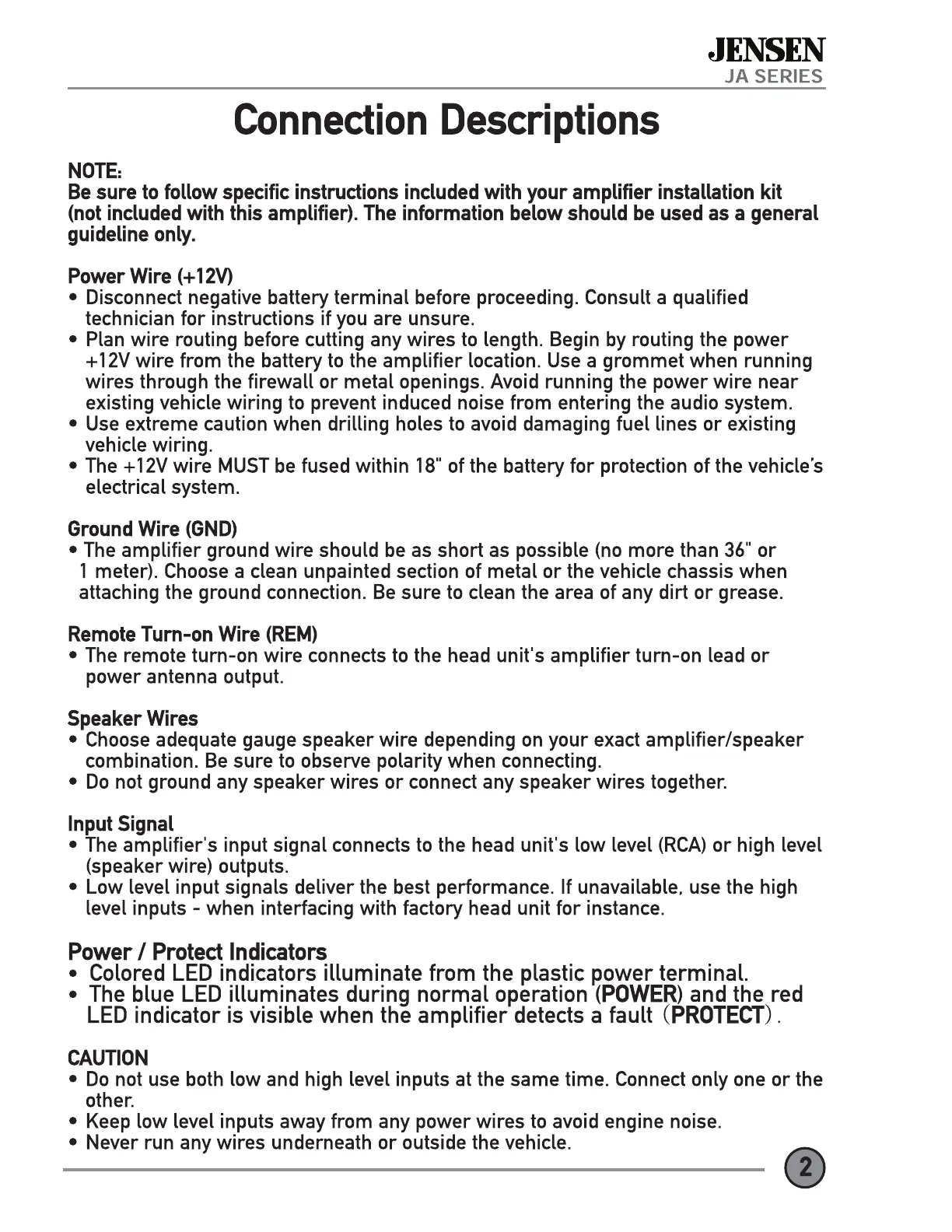
• Colored
LED
indicators illuminate from the plastic power terminal.
•
The
blue
LED
illuminates during normal operation
(POWER)
and the red
LED
indicator is visible when the amplifier detects a fault
(PROTECT).
CAUTION
•
Do
not use both low and high level inputs at the same time. Connect only one
or
the
other.
• Keep low level inputs away from any power wires to avoid engine noise.
• Never run any wires underneath
or
outside the vehicle.


 To Next Page