EasyManua.ls Logo

Jensen XA2150 - User Manual

Jensen XA2150
12 pages
Print Icon
To Next Page IconTo Next Page
Loading...
How to Install and Operate
the XA2150 Amplifier
®
Contents
Technical Assistance
For technical assistance with the operation or installation
of the XA2150, call 1-800-323-0221.
Welcome!
What you're holding in your hands is no ordinary
owner's manual. We've tried to make the instructions
in this book clear and easy to follow.
For your Jensen amplifier to work right, it must be
installed correctly. This manual will show you how to
install your new amplifier like a pro. It's a good idea to
read all of these instructions before you begin the
installation. Most installations are straightforward and
can be handled by a do-it-yourselfer with the right
tools, patience, and the ability to follow instructions.
But, do-it-yourself installation isn't for everyone. If you
still don't feel confident after reading this book,
consider turning the installation job over to someone
better suited to it.
Warranty Service
If your Jensen amplifier should ever require service,
you will need to have the original dated receipt. If you
ever need to return the unit for any reason, always
include the receipt with the product.
Features........................................ 2
Installation................................... 2
Before You Begin
Installation .....................................2
Amplifier Location ..........................2
Disconnect Battery ........................2
Amplifier Installation Kit .............2
Supplies and Tools
Needed ..........................................3
Routing Wires ................................3
Bigger is Better ..........................3
Wiring............................................. 4
Power and Outputs ........................4
Power Terminal (BATT +12V) ........4
Ground Terminal (GND).................4
Remote Terminal (RMT +12V).......4
Fuses .............................................4
Inputs and Controls .......................5
Input Wiring....................................5
Pass Output ...................................5
Power Light....................................5
Protect Light ..................................5
Input Level Control ........................6
Bass Boost.....................................6
Crossover ......................................6
Speaker Wiring ..............................7
Testing .......................................... 9
Reconnect Battery .........................9
Test Power Wiring..........................9
Test Speaker Connections ............9
Dealing with Alternator
Noise..........................................9
Installing in Trunk.....................10
Crimp Connections ..................10
Securing Wires ........................10
Speaker and
Power Wires ............................10
Troubleshooting ....................... 11
Specifications
and Warranty............................. 12
50 250
HPF
ON
OFF
BASS
-BOOST
POWER
PROTECT
HIGH INPUT
LOW
PASS OUTPUT
LR
LR
LEVEL
MIN MAX
LPF
50 250
®
HPF
LPF
FULL
X-OVER
5311Eamp.p65 4/10/99, 8:13 PM1
Question and Answer IconNeed help?

Do you have a question about the Jensen XA2150 and is the answer not in the manual?

Summary

Technical Assistance

Features

Installation

Before You Begin Installation

Prepare necessary tools, supplies, and adapters before commencing installation.

Amplifier Location

Select a mounting location allowing adequate air circulation to prevent overheating.

Disconnect Battery

Always disconnect the vehicle's negative battery terminal before starting installation.

Supplies and Tools Needed

Routing Wires

Wiring

Power Terminal (BATT +12 V)

Connect directly to the vehicle battery positive terminal using 8 gauge wire.

Remote Terminal (RMT +12 V)

Connect the radio power antenna lead to turn the amplifier on/off with the receiver.

Ground Terminal (GND)

Connect to clean, unpainted metal chassis for a good electrical ground connection.

Fuses

Use only one 30 amp blade-type fuse for protection.

Inputs and Controls

Input Wiring

Connect low-level RCA or high-level speaker wires from the receiver to the amplifier inputs.

Pass Output

Use pass-through connectors for adding other amplifiers to the system.

Power Light

Indicator light shows when 12-volt power is available at the battery and RMT wires.

Protect Light

Indicates amplifier shutdown due to overheating, short circuit, or speaker failure.

Input Level Control

Crossover (X-OVER)

Bass Boost

Speaker Wiring Configurations

2 Speakers

Connect two speakers to the amplifier's stereo outputs.

2 Subwoofers

Connect two subwoofers to the amplifier's stereo outputs.

Advanced Speaker Wiring

2 Speakers + Subwoofer (Tri-mode)

Connect two full-range speakers and one subwoofer using appropriate crossovers.

Bridged Subwoofer

Connect a single subwoofer to the amplifier in bridged mode for maximum power.

Testing

Reconnect Battery

Reconnect the negative battery terminal after all wiring is complete and verified.

Test Power Wiring

Verify amplifier power light comes on and speakers operate when receiver volume is adjusted.

Test Speaker Connections

Ensure correct speaker output and verify wiring if sound is absent or incorrect.

Dealing with Alternator Noise

Prevent 'siren' sound by not bundling cables, running wires separately, and ensuring good grounds.

Installation Tips

Trunk Installation Routing

Run power wires along existing vehicle wiring paths in the trunk, removing trim as needed.

Wire Bundling and Securing

Use wire ties to bundle wires, keeping power and speaker wires separate for optimal performance.

Proper Crimp Connections

Strip 1/4 inch insulation, insert into connector, and crimp securely for reliable splices.

Separating Power and Speaker Wires

Run power and speaker wires on opposite sides of the vehicle to prevent noise induction.

Troubleshooting

Amplifier No Power

Check +12V and remote wires for power. Verify fuse status.

Low Amp Output

Adjust input level control (gain) to a higher setting if radio volume is too high.

Input Sensitivity Issues

Adjust input level control to a lower setting if radio volume is too sensitive.

Single Speaker Output

Check speaker connections, wiring integrity, and for defective speakers.

Distorted Sound

Adjust input level, check speaker wiring for shorts, and ensure RCA cables are functional.

Blown Fuses

Verify power wire connections and check speakers for shorts or defects.

Alternator Noise

Ensure proper ground connections and separate power/speaker wires to avoid ignition noise.

Power On;Off Pops

Check remote wire connection; consider a switch for manual amp turn-on if needed.

Amplifier Shutdown

Allow amplifier to cool if in thermal protection; check speaker connections and impedance.

No Output on Channels

Verify speaker wires are connected correctly to speakers and inputs are properly hooked up.

General Troubleshooting

Refer to specific sections or contact Jensen Technical Assistance for unresolved issues.

Specifications

Overview

The Jensen XA2150 is a two-channel, 300-watt total system power automotive amplifier designed to enhance the audio experience in a vehicle. This amplifier is built to make the sound of your receiver fuller and richer, even at low volume levels, and allows for the use of more powerful speakers by delivering substantial wattage per channel.

Function Description

The primary function of the XA2150 amplifier is to boost audio signals from a car's receiver to drive speakers with greater power and clarity. It features RCA inputs for low-level audio signals and high-level inputs for direct connection to speaker outputs from a receiver, offering flexibility in integration with various car audio systems. The amplifier includes a continuously variable low-pass or high-pass crossover, allowing users to tailor the frequency response to specific speaker types, such as subwoofers (low-pass filter) or smaller full-range speakers (high-pass filter). A "full" setting is also available for full-range speakers, passing all tones.

A bass boost feature is incorporated, which increases the volume of bass by up to 6 dB at 45Hz, providing a more impactful low-frequency response. The amplifier also has a remote turn-on/off capability, which allows it to power on automatically when the car's receiver is turned on, simplifying operation.

For system expansion, the XA2150 includes pass-through connectors, enabling the addition of other amplifiers to the audio setup. Its bridgeable design allows the amplifier to direct its full power to a single speaker, typically a subwoofer, for enhanced bass performance.

Usage Features

Installation and Setup:

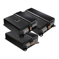
The XA2150 is designed for flexible mounting, either under a seat or in the trunk, thanks to its compact design. Proper air circulation around the amplifier is crucial due to heat generation, so it should not be covered by carpets or enclosed behind trim panels. The installation process requires disconnecting the battery's negative terminal for safety. An amplifier installation kit is highly recommended, as it typically includes necessary components like RCA cables, power and ground wires, and a fuse or circuit breaker.

Wiring:

  • Power Terminal (BATT +12V): Connects directly to the vehicle battery's positive terminal using an 8-gauge wire (minimum). A 30-amp fuse or circuit breaker should be installed as close to the battery as possible for protection.
  • Ground Terminal (GND): Connects to a clean, unpainted metal chassis ground to ensure a good electrical connection.
  • Remote Terminal (RMT +12V): Connects to the radio's power antenna lead or an accessory fuse. This allows the amplifier to turn on and off with the receiver.
  • Fuses: The amplifier uses a single 30-amp blade-type fuse for protection.

Input Wiring:

The amplifier supports both high-level and low-level inputs, but only one type should be used at a time.

  • Low-Level Input: Utilizes shielded stereo audio cables with RCA type jacks, connecting from the receiver's low-level outputs to the amplifier's RCA input jacks.
  • High-Level Input: Connects directly to the speaker wires from the radio using the provided high-level input plug.

Pass Output:

Pass-through connectors (PASS OUTPUT) are available for daisy-chaining and adding other amplifiers to the system.

Controls:

  • Input Level Control: Matches the output of the radio to the amplifier's input. It should be adjusted by first setting the radio's volume to just below distortion, then slowly increasing the amplifier's input level until distortion is heard, and finally backing off slightly.
  • Crossover (X-OVER): Allows selection between LPF (low-pass filter) for subwoofers, HPF (high-pass filter) for smaller speakers, or FULL for full-range speakers. The LPF and HPF frequencies can be adjusted from 50 to 250Hz. When running a subwoofer and two full-range speakers (Tri-mode operation), separate high and low pass crossovers must be used to prevent damage to the amplifier and speakers.
  • Bass Boost: An ON/OFF switch to activate or deactivate the 6 dB bass boost at 45Hz.

Speaker Wiring:

The manual provides diagrams for various speaker configurations, including two speakers, two subwoofers, two speakers plus a subwoofer, and a bridged subwoofer. It emphasizes the importance of using appropriate speaker wire gauges (12 gauge for subwoofers, 16-18 gauge for other speakers) and ensuring correct impedance matching (e.g., 4 ohms minimum for bridged operation).

Testing:

After installation, several tests should be performed:

  1. Reconnect Battery: Reconnect the battery's negative terminal.
  2. Test Power Wiring: Turn on the receiver (without volume) and check if the amplifier's power light comes on. If not, check the RMT and +12V wires.
  3. Test Speaker Connections: Slowly increase the receiver volume and ensure all speakers operate correctly. Check for proper connections if any speaker does not play or if the wrong speaker plays.

Maintenance Features

Electronic Protection Circuitry:

The XA2150 is equipped with electronic protection circuitry to safeguard against short circuits, DC offset, and thermal overload.

  • Power Light: Indicates that 12-volt power is available to both the battery +12V and RMT wires.
  • Protect Light: A red light that illuminates when the amplifier shuts down due to overheating or a short circuit (e.g., speaker failure). If this light comes on, the amplifier needs to cool down before it can operate again. In some installations, especially when driving subwoofers, a fan might be necessary to keep the amplifier cool.

Troubleshooting:

The manual includes a comprehensive troubleshooting guide to address common issues such as:

  • Amplifier not operating (no power LED).
  • Radio volume needing to be too high or too sensitive.
  • Sound from only one speaker or distorted sound.
  • Blown fuses.
  • Alternator whine in outputs.
  • Loud pop in speakers when turning on/off.
  • Protect light coming on.
  • No output on channels.

The guide provides possible causes and corrective actions, such as checking wiring connections, adjusting input levels, replacing defective speakers, insulating speaker wires, and ensuring proper grounding.

Professional Tips:

  • Bigger is Better: Using extra thick power and speaker wires (e.g., 8 gauge power wire) is recommended for optimal sound, especially with multiple amplifiers.
  • Installing in Trunk: Run power wires along existing vehicle wiring paths, often requiring removal of door sill trim and carpet.
  • Crimp Connections: Use crimp connectors and a crimping tool for secure wire connections. Strip 1/4 inch (6mm) of insulation, insert into the connector, and crimp tightly.
  • Securing Wires: Use wire ties to bundle loose wires to the vehicle to prevent rubbing or rattling. However, never bundle speaker wires and power wires together.
  • Speaker and Power Wires: Run speaker and power wires on opposite sides of the car to prevent "siren" noise from power wires interfering with speaker signals.
  • Dealing with Alternator Noise: To prevent alternator whine, avoid bundling RCA cables with speaker or power wires, do not run speaker wires parallel to power wires, connect all ground wires to the same screw if using multiple amplifiers, keep all wires as short as possible, and ensure the receiver's black wire has a good connection to the vehicle chassis ground.

The Jensen XA2150 amplifier is designed for car audio enthusiasts looking to upgrade their in-vehicle sound system with a powerful, versatile, and protected amplification solution.

Jensen XA2150 Specifications

Power Output IconPower Output
power output at 4 ohms75 Watts per channel RMS
power output at 2 ohms100 Watts per channel RMS
bridged power output at 4 ohms200 Watts per channel RMS
Audio Performance IconAudio Performance
frequency response20 Hz-20 kHz ± 3 dB
signal to noise ratio at rated power>100 dB
channel separation at reference power>65 dB, 1 kHz
Electrical Specifications IconElectrical Specifications
power requirement14.4 VDC (10.8-15.6 VDC allowable)
fuse requirements30 amp blade-type fuse
speaker impedance2-8 ohms
Physical Specifications IconPhysical Specifications
dimensions2.25" x 11.125" x 8" (56.5mm x 282mm x 203mm)
input impedance20 k ohms
crossover frequenciesLow/High: 50-250 Hz

Related product manuals