6
WIRING
The wiring diagram depicts all the wiring connections required for proper operation of the unit.
DETAIL A
SHOWN FROM PIN VIEW
FRONT RIGHT (A) SPEAKER (+)
FRONT RIGHT (A) SPEAKER (-)
FRONT LEFT (A) SPEAKER (-)
FRONT LEFT (A) SPEAKER (+)
AMP REMOTE (+12VDC 100mA)
RIGHT REAR (A) SPEAKER (+)
RIGHT REAR (A) SPEAKER (-)
LEFT REAR (A) SPEAKER (-)
LEFT REAR (A) SPEAKER (+)
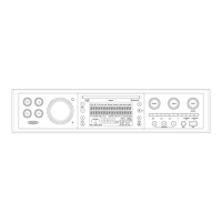
CONNECTIONS
The diagram below depicts all the available audio/video connections available to use with your
system.
WARNING: Wiring harness comes with stripped and tinned leads to aid in the
installation process. Any unused speaker wires must have their exposed ends cut off or
insulated individually.

 Loading...