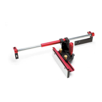
STEP A:
Using a combination square or mitre square, check to see if
the fence is at 45°. See Figure 24.
(We have used a combination square and a ruler along
the fence to check the angle)
Iffyour fence is not at 45°, follow step B, C, D and E.
FIGURE 24
FIGURE
2
5
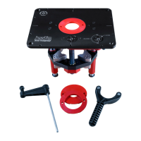
STEP B:
Ensure the gauge is fully in the 45° position. See Figure 25.
10
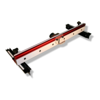
STEP C:
Loosen the Mite-R-Slide II
fence clamping knobs,
(Part #42). See Figure 26.
FIGURE 26
FIGURE 27
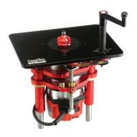
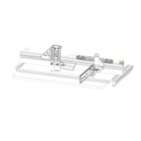
STEP D:
Slide the Mite-R-Slide II fence (Part #4) further along the gauge .
See Figure 27.
You will see a second set screw Part #41.
a)
If your Mite-R-Slide II is out of square and has a gap closer to
your router fence, you will want to tighten the set screw a little
bit. Depending on how far out it is, a quarter turn (clockwise) is
all it may need.
b)
If your Mite-R-Slide II is out of square and has a gap closer to
the front of your router table you will want to loosen the set screw
a little bit. Again, depending on how far out your Mite-R-Slide II
fence is, a quarter turn (counter clockwise) is all it may need.
STEP C:
With the 1/8" Hex Key provided you will either loosen or tighten up
the set set screw. See Figure 23.
FIGURE 23
CALIBRATING FENCE
TO “
45°”
 Loading...