12
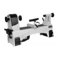
Fig 10
Face locate the workpiece for added support.
6.2 Tool setup
The cutting angle is correct when the cutting edge is in
line with the centre axis of the work piece. Use the point
of the tailstock centre as a gauge and shims under the
tool to obtain the correct centre height.
Use a minimum of two clamping screws when installing
the cutting tool to the four way tool post.
Avoid big tool extensions.
6.3 Spindle speeds selection
The correct spindle speed depends on the type of
machining, the cutting diameter, the material to be
machined and the cutting tool.
These are recommended max. speeds for a 50mm
cutting diameter with carbide (HM) tools:
Aluminium, brass 1500 RPM
Cast iron 1000 RPM
Mild steel 800 RPM
High carbon steel 600 RPM
Stainless steel 300 RPM
If high speed steel (HSS) tools are used about 5 times
lower speeds must be chosen.
Generally speaking, the larger in relation the cutting
diameter, the smaller the possible RPM.
For example:
Turning mild steel at a diameter of 25mm allows a
speed of
1600 RPM max. with carbide tool
320 RPM max. with HSS tool
To change the spindle speed:
The speed may never be changed when the spindle
or motor are still running.
Move the speed select levers (2, Fig 1) according to
the speed you desire.
It may be necessary to turn the chuck by hand to help
the gears to engage.
6.4 Turning with auto feed
Several automatic longitudinal and cross feeds are
readily available by selection on the gearbox levers
(20, 22, 23, Fig 1).
Do not shift levers while the machine is running.
Move the feeding lever (14, Fig 2):
- left /right for longitudinal feed.
- up/down for cross feed
The correct feed depends on the material to be
cut, the cutting operation, the type of tool, the
rigidity of the work piece chucking, the depth of
cut and the desired surface quality.
For example:
Longitudinal OD-turning, mild steel of 25mm diameter
with a carbide tool at 1200 RPM and with rigid
chucking.
Stock removal and roughing cut:
Depth of cut 2mm
Feed per revolution 0,25mm
Finishing cut:
Depth of cut 0,5mm
Feed per revolution 0.1mm
 Loading...