Do you have a question about the Jet GH-1640ZX and is the answer not in the manual?
Key safety guidelines covering manual comprehension, PPE, operation, and machine maintenance.
Details covered defects, exclusions, and limitations for product use.
Provides contact information and procedure for technical assistance and product info.
Outlines warranty duration, state law applicability, and liability limits.
Detailed specifications for the 14-inch model of the lathe.
Detailed specifications for the 16-inch model of the lathe.
Detailed specifications for the 18-inch model of the lathe.
Detailed specifications for the 22-inch model of the lathe.
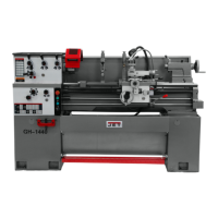
Explains the main parts of the lathe, including bed, headstock, carriage, and components.
Details various accessory components and their functions.
Lists all parts and accessories included in the lathe's shipping container.
Detailed steps for leveling the lathe for accuracy.
Instructions for cleaning rust protection and lubricating gears.
Procedures for installing, removing, and handling the three-jaw chuck.
Guidelines for the initial break-in period to adapt gears and bearings.
Details lubrication for headstock, gearbox, apron, and leadscrew/feed rod.
Lubrication for saddle, rest, slide, tailstock; V-belt maintenance.
Steps to convert the machine's electrical system from 230V to 460V.
Identifies and explains the functions of the headstock control panel buttons and lights.
Details how to set spindle speed, feed direction, and feed/lead selection.
Details handwheels, levers, locks, and adjustments for carriage and tailstock.
Provides guidance on cutting speeds, feeds, and essential operating cautions.
Procedures for tool setup, feed selection, and thread cutting operations.
Steps to reverse the three-jaw chuck jaws for larger diameter stock.
Adjusting gibs for saddle, cross slide, and compound rest to reduce play.
Adjusting half nut gibs and offsetting the tailstock for taper cutting.
Steps for removing the gap bridge from the lathe bed.
Procedures for installing the gap bridge and maintaining V-belts.
Aligning tailstock to headstock and adjusting cross slide nut backlash.
Replacing shear pins and adjusting the steady rest.
Adjusting the follow rest and carriage stops for proper operation.
Lubrication schedule for headstock and gearbox oil changes.
Lubrication for apron, saddle, cross slide, and compound rest.
Covers tailstock, felt cleaning, coolant, belts, and rest lubrication.
Table detailing longitudinal and transverse feed rates in inches per revolution.
Chart to select threading parameters for inch threads.
Charts for selecting metric and module pitch threading parameters.
Chart for selecting diametral pitch threading parameters.
Exploded view and part list for the lathe's stand assembly.
Exploded view and part list for the lathe's brake assembly.
Exploded view and part list for the lathe's bed assembly.
Exploded views and part lists for all four headstock assembly sections.
Exploded views and part lists for all change and quick change gear boxes.
Exploded views and part lists for all three apron assembly sections.
Exploded view and part list for the carriage assembly.
Exploded views and part lists for both tailstock assembly sections.
Exploded views and part lists for steady and follow rest assemblies.
Exploded view and part list for the coolant and work light assembly.
Parts list and breakdown diagram for the electrical cabinet.
Exploded view and part list for the safety guard cover.
Exploded view and part list for the carriage lubrication system.
| Swing Over Bed | 16 inches |
|---|---|
| Distance Between Centers | 40 inches |
| Spindle Bore | 2.05 in |
| Motor Power | 2 HP |
| Spindle Speed Range | 70 - 1, 800 RPM |
| Motor | 2 HP |