M
Martin AdamsAug 17, 2025
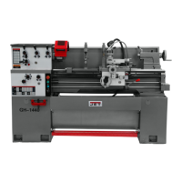
Why is my Jet GH-1640ZK overheating?
- MMichael AllisonAug 17, 2025
If your Jet Lathe is overheating, it might be bogging down in the cut due to an excessive feed rate or depth of cut. Try decreasing the feed rate or depth of cut.