21
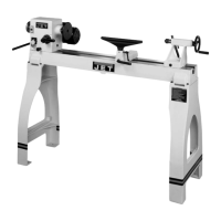
Figure 32 – Tailstock offset adjustment
13.4 Gap section
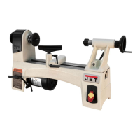
1. To remove the gap section (Figure 33),
remove four socket head cap bolts (A) and two
socket bolts at the ends of the rails (B).
2. Remove two tapered alignment pins (C) by
placing the provided gap bridge pin driver (D)
over them and threading its screw down into
them, until the pins are loosened enough to be
pulled out.
3. Remove gap section.
Figure 33 – Gap section
To reinstall gap section:
1. Thoroughly clean bottom and ends of gap
section.
2. Set gap section in place and align the ends.
3. Insert the tapered pins into their holes through
gap and into lathe bed.
4. Re-insert the six bolts (A,B) and tighten
alternately until all are snug. Make sure gap
remains aligned with ways while tightening
screws.
13.5
Belt Adjustment and replacement
The belts should be inspected periodically. New
belts have a tendency to stretch slightly after a
short period of use; and prolonged use will require
that they be tightened to compensate for normal
wear.
NOTE: If a worn, cracked or frayed belt needs
replacing, replace all three as a matched set.
To adjust or replace belts:
1. Disconnect machine from power source.
2. Open end gear cover, remove lower rear cover
and lower side cover. This will expose motor
and v-belts.
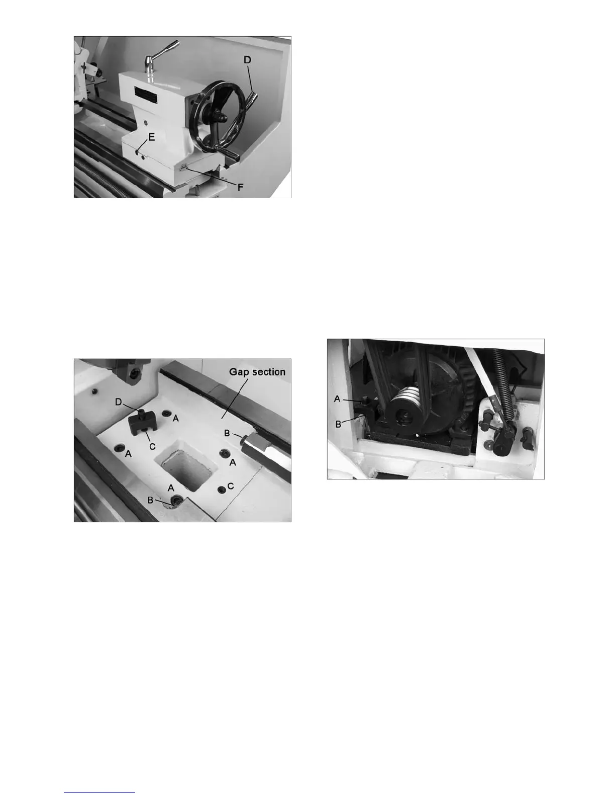
3. Loosen upper hex nut (A, Figure 34). Place
scrap piece of wood under motor to act as
lever. Lift motor up and block temporarily.
4. Remove belts. Install new belts onto pulleys.
5. Lift up on motor and remove temporary
blocking.
6. Tension belts by loosening lower nut (B,
Figure 34) and tightening down upper nut (A,
Figure 34) until light finger pressure causes
approximately 3/4” deflection on each belt.
7. Install covers and connect lathe to power
source.
Figure 34 – Belt adjustment
13.6 Aligning tailstock to headstock
Headstock and Tailstock have been aligned at the
factory and should not require attention. If future
adjustment should ever be needed, proceed as
follows. (Make sure that twist in the lathe bed is not
contributing to the problem; refer to sect. 8.1.)
1. Fit a 12” ground, center-drilled, steel bar
between centers of headstock and tailstock
(Figure 35).
2. Fit a dial indicator to the top slide and traverse
the center line of the bar. If it indicates a taper,
adjustment is needed.
3. Align tailstock using the off-set screws at front
and back (see E, Figure 32) until tailstock is
aligned.

 Loading...