22
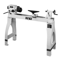
Figure 35 – Tailstock/Headstock alignment
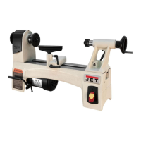
13.7 Cross slide nut adjustment
The cross slide moves via a lead screw which
drives a nut. This can be adjusted if backlash
develops. Backlash is identified by turning the
cross slide handwheel left and right – if there is a
delay before any cross slide movement, the nut
needs adjusting.
Tighten or loosen the two screws shown in Figure
36 until backlash is adjusted out.
Figure 36 – Cross slide nut adjustment
13.8 Shear pin replacement
The lead screw and feed shaft are equipped with
shear pins, which are designed to break in order to
protect the drive system against overload. A
broken shear pin must be replaced.
Knock out the broken pin; line up the holes and
insert new pin.
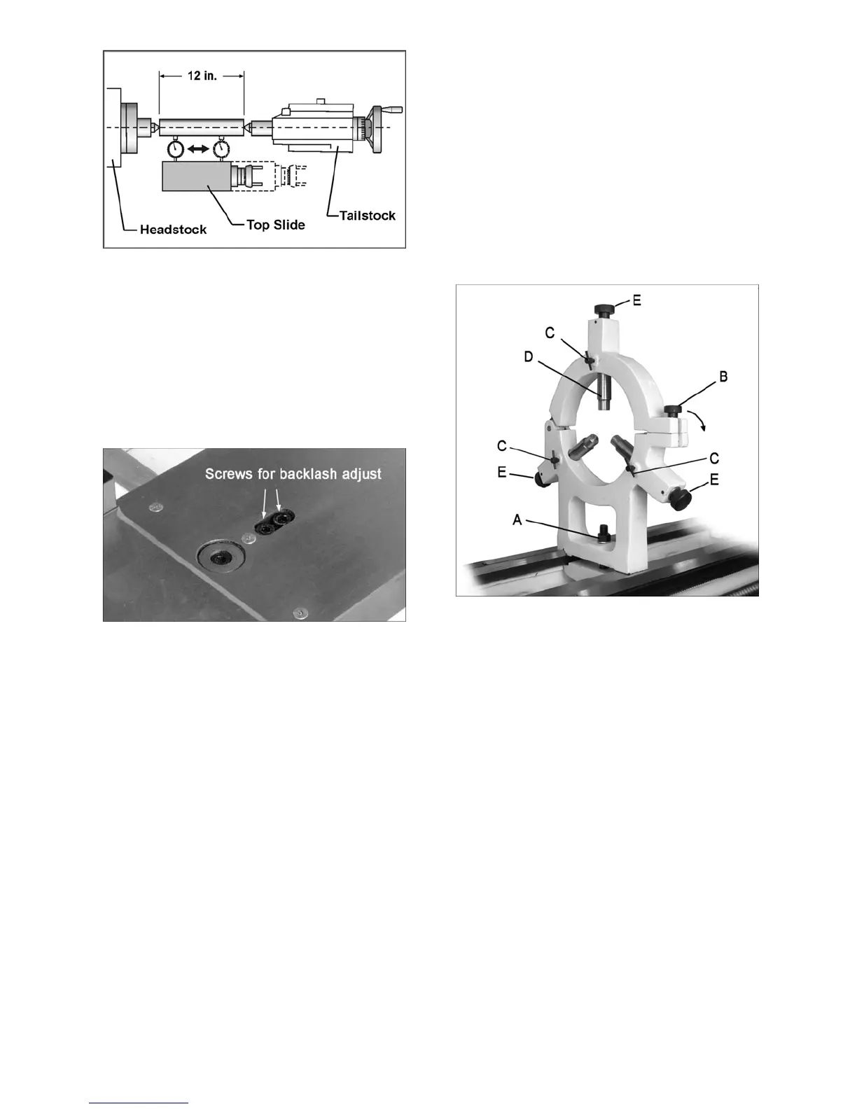
13.9 Steady rest adjustment
Always lubricate the fingers with grease before
using the steady rest. The point at which the
fingers contact the workpiece require continuous
lubrication to prevent premature wear.
To set the steady rest (see Figure 37):
1. Loosen hex nut (A) to slide steady rest along
the ways.
2. Loosen knurled handle (B) until it can be
pivoted out of the slot.
3. Loosen three lock knobs (C), and back off the
fingers (D) using knurled handles (E).
4. Pivot the collar on its hinge and position
steady rest around workpiece.
5. Firmly tighten hex nut (A).
6. Set the fingers snugly to work piece and
secure by tightening locking knobs. Fingers
should be snug but not overly tight.
Figure 37 – Steady rest adjustment
13.10 Follow rest adjustment
The follow rest mounts to the saddle with two
socket head cap bolts. The follow rest should be
mounted so that locking knobs point away from
chuck.
The sliding fingers are set similar to those on the
steady rest – free of play, but not binding.
Always lubricate the fingers sufficiently with grease
before operating.

 Loading...