7
Range of Modular Threads ..................................................................................................................0.25-10M.P.
Leadscrew Pitch .............................................................................................................................................. 1/4”
Tailstock:
Tailstock Spindle Travel .................................................................................................................... 6” (152.4mm)
Tailstock Taper.............................................................................................................................................. MT-4
Maximum Tailstock Cross Displacement ....................................................................................... +/- 0.40” (10mm)
Other:
Steady Rest Capacity .......................................................................................................... 3/8 - 4” (9.5 x 102mm)
Follow Rest Capacity ................................................................................................. 1/2" – 3-1/8” (12.7 x 79.4mm)
Coolant tank capacity (approximate) ..................................................................................................... 4 gal. (15L)
Noise emission (idling at max. speed)
1
......................................................................................................... 85 dB
Overall Dimensions ..................................................................... 91”L x 42-1/8”W x 49”H (2311 x 1070 x 1245mm)
Shipping Weight ...........................................................................................................................3630 lb (1647kg)
Net Weight ...................................................................................................................................4159 lb (1887kg)
1
Values are emission levels, not necessarily to be seen as safe operating levels. Since workplace conditions vary, this
information is only intended to allow the user to make a better estimation of the hazards involved.
The specifications in this manual were current at time of publication, but because of our policy of continuous improvement,
Walter Meier (Manufacturing) Inc., reserves the right to change specifications at any time and without prior notice, without
incurring obligations.
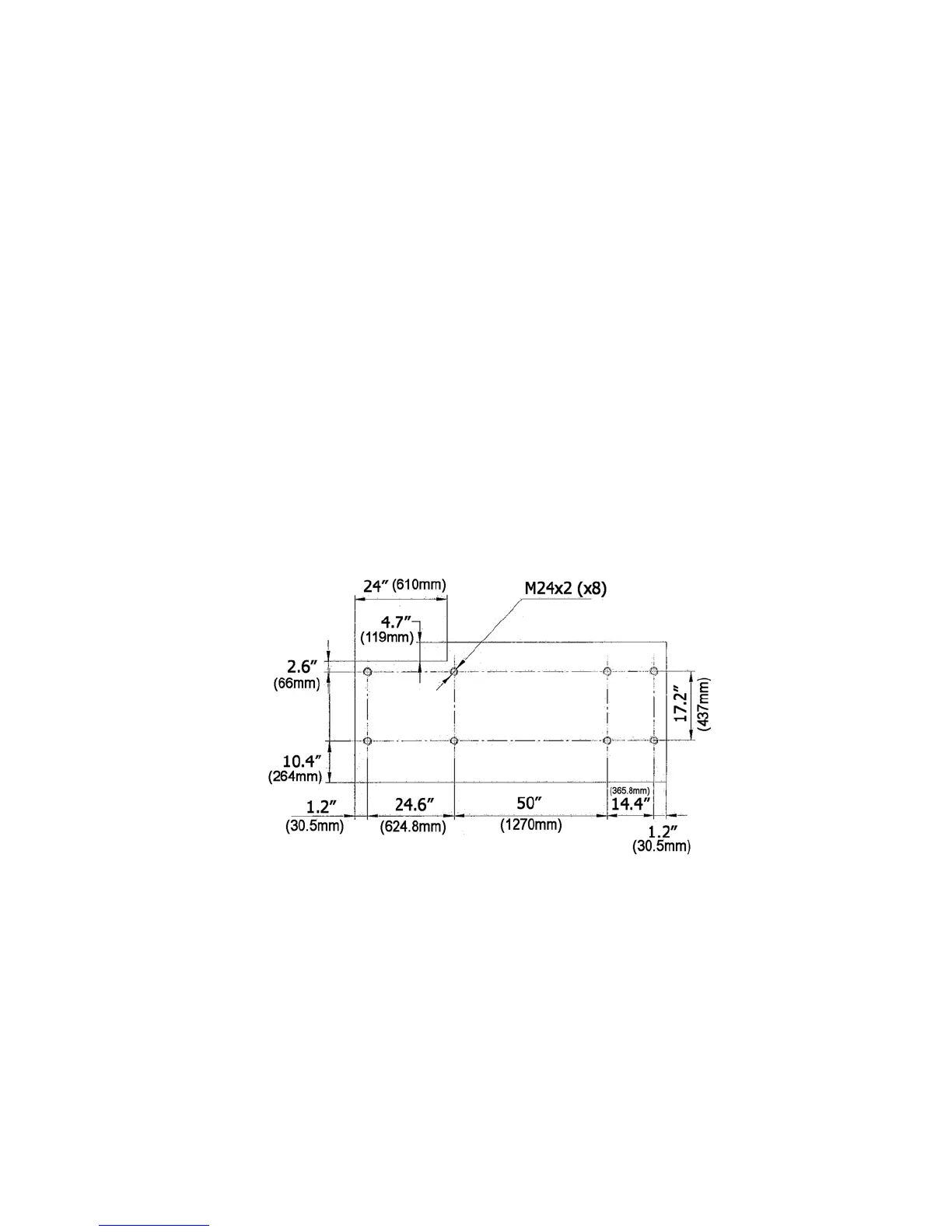
5.0 Dimensions and mounting hole centers
Figure 1

 Loading...