Read and understand the
entire contents of this manual before
attempting set-up or operation. Failure to
comply may cause serious injury.
8.0 Installation
1. Finish removing all crate material from around
lathe.
2. Unbolt lathe from shipping pallet.
3. Choose a location for the lathe that is dry and
has sufficient illumination (consult OSHA or
ANSI standards for recommended lighting
levels in workshop environments).
4. Allow enough room to service the lathe on all
four sides, and to load and off-load work
pieces. In addition, if bar work is to be
performed, allow enough space for stock to
extend out the headstock end. If used in
production operations, leave enough space for
stacking unfinished and finished parts.
5. The foundation must be solid to support the
weight of the machine and prevent vibration,
preferably a solid concrete floor.
6. The lathe’s center of weight is near the
headstock. Before lifting, move the tailstock
and the carriage (release carriage lock, see
section 11.0) to the right end of the bed and
lock them.
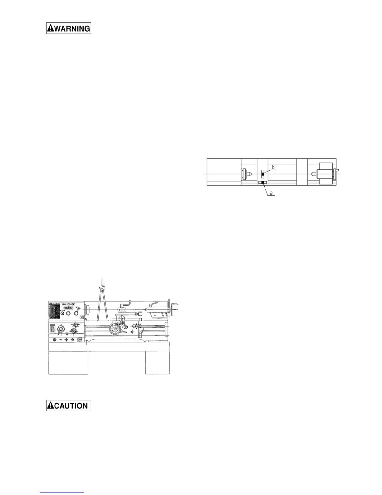
7. With properly rated lifting equipment, slowly
raise lathe off shipping pallet. (see Figure 4).
Do not lift lathe by the spindle.
Figure 4 – Lifting the lathe
Confirm that all suspension
equipment is properly rated and in good
condition for lifting lathe. Do not allow anyone
beneath or near load while lifting.
8. The lathe can be placed upon the cast iron
leveling pads under each foot hole, and
adjusted using the adjusting bolts with hex
nuts. Or, it may be secured to the floor using
bolts placed head-down in the concrete, and
using shims where needed to level the
machine. Refer to Figure 1 for mounting hole
dimensions.
8.1 Leveling the lathe
It is imperative that the lathe be on a level plane;
that is, where headstock and tailstock center points
remain aligned throughout the tailstock travel, with
the bed ways absent of twist and thus parallel to
the operational center line.
A lathe which is not properly leveled will be
inaccurate, producing tapered cuts. Also, the
center point of the tailstock will vary as it is
positioned along the bed, thus requiring constant
readjustment of the set of the tailstock.
Figure 5 – Leveling
9. Use a machinist’s precision level on the bed
ways both front to back and side to side, as
shown in Figure 5. Take the reading in one
direction every ten inches. Make sure the ways
are clean and free of any debris before placing
a level upon them.
10. Deviation over bed length (see Figure 5):
(a) Maximum 0.02/1000mm
(b) Maximum 0.04/1000mm
11. Tighten foot screw nuts evenly to avoid
distortion.
12. Leveling should be inspected occasionally,
and especially if the accuracy of the lathe
begins to diminish.
8.2 Completing installation
13. Exposed metal surfaces have been coated
with a rust protectant. Remove this using a soft
rag and mild commercial solvent or kerosene.
Do not use paint thinner, gasoline, or lacquer
thinner, as these will damage painted
surfaces. Cover all cleaned surfaces with a
light film of SAE-20W machine oil, such as
Mobil DTE Oil Heavy Medium.
14. Open the end gear cover. Clean all
components of the end gear assembly and
coat all gears with a heavy, non-slinging
grease. Close the end gear cover. (Note: A
limit switch prevents the lathe from operating
when the end gear cover is open.)

 Loading...