16
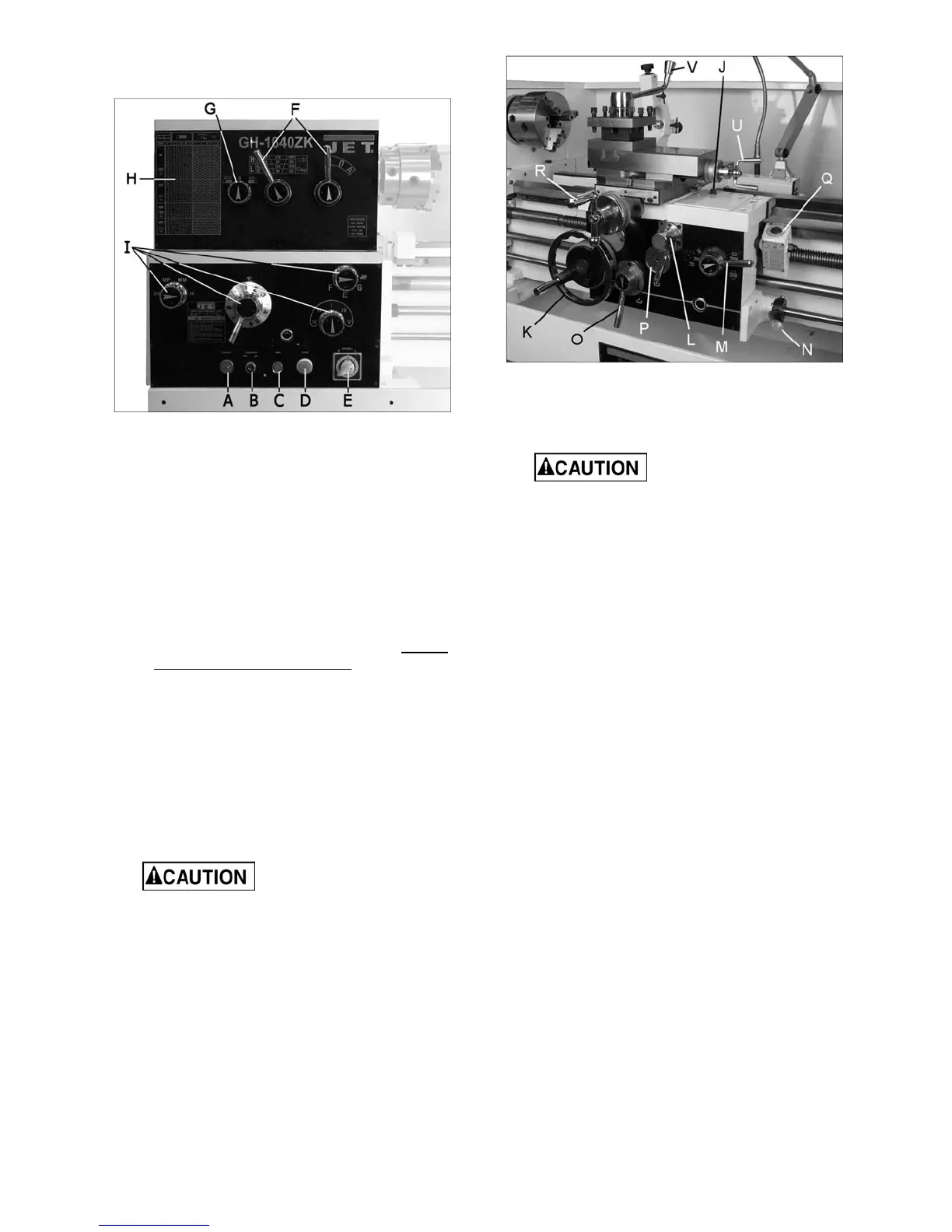
11.0 Basic controls
Figure 19 – Headstock Controls
1. Control Panel: Located on front of headstock.
• Power Indicator Light (A, Figure 19).
Illuminates whenever lathe is receiving
power.
• Coolant On-Off Switch (B, Figure 19).
Activates coolant pump.
• Jog Button (C, Figure 19). Quickly press
and release to rotate spindle.
• Emergency Stop Button (D, Figure 19).
Shuts down all machine functions. NOTE:
Lathe will still have power. Twist button
clockwise to reset.
• Motor Speed Switch (E, Figure 19). Turn to
select high or low speed.
2. Speed Selection Levers (F, Figure 19): Move
levers left or right to desired spindle speed,
according to accompanying chart.
3. Feed Direction Knob (G, Figure 19): Rotating
the knob changes direction of feed. Center
position is neutral.
Do not move feed
direction knob (G) while machine is
running.
4. Lead and Feed Selector Levers (I , Figure
19): Used conjunctively to set up for threading
or feeding, according to the accompanying
chart (H, Figure 19).
Figure 20 – Carriage controls and settings
5. Carriage Lock (J, Figure 20): Located on top
right of carriage. Turn clockwise to lock,
counterclockwise to unlock.
Carriage lock must be
loose before moving carriage or damage to
lathe may occur.
6. Carriage Handwheel (K, Figure 20): Located
on the apron. Rotate handwheel clockwise to
move the carriage assembly toward the
tailstock (right). Rotate the wheel
counterclockwise to move the carriage
assembly toward headstock (left). A scale is
mounted to the ring, graduated in 0.005 inch
increments, and can be calibrated by
loosening the thumb screw lock and rotating
the ring as needed. Always retighten ring
before using the feed.
7. Feed Direction Lever (L, Figure 20): Push to
one of three positions; Up for crossfeed; Down
for longitudinal; the middle position allows
screws to be cut by engaging the half nut.
8. Half Nut Lever (M, Figure 20): Located on the
front of the apron assembly. Engages the
leadscrew for threading operations.
9. Spindle Direction Control Lever (N, Figure
20). Move the lever to the right so that its tab
clears the notch, then down for forward spindle
rotation, or up for reverse spindle rotation.
Allow the spindle to come to a stop before
changing directions. Position lever in neutral
position (tab in notch) before shutting off the
lathe.
10. Feed Engagement Lever (O, Figure 20): Pull
up to engage, down to disengage.
11. Adjustable Feed Clutch (P, Figure 20): The
clutch may slip if the machine is overloaded;
cutting rate must be reduced. The setting of
the clutch has been adjusted at the factory and
should not require attention. If future

 Loading...