15
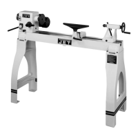
Figure 15 – Lubrication points
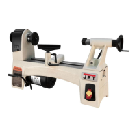
13. Tailstock – Daily lubricate two ball oilers
(Figure 16) on top of tailstock.
The anti-dust felt beneath the tailstock that
runs along the ways should be cleaned weekly
with kerosene. If the felts become damaged,
replace them.
Figure 16 – Tailstock lubrication
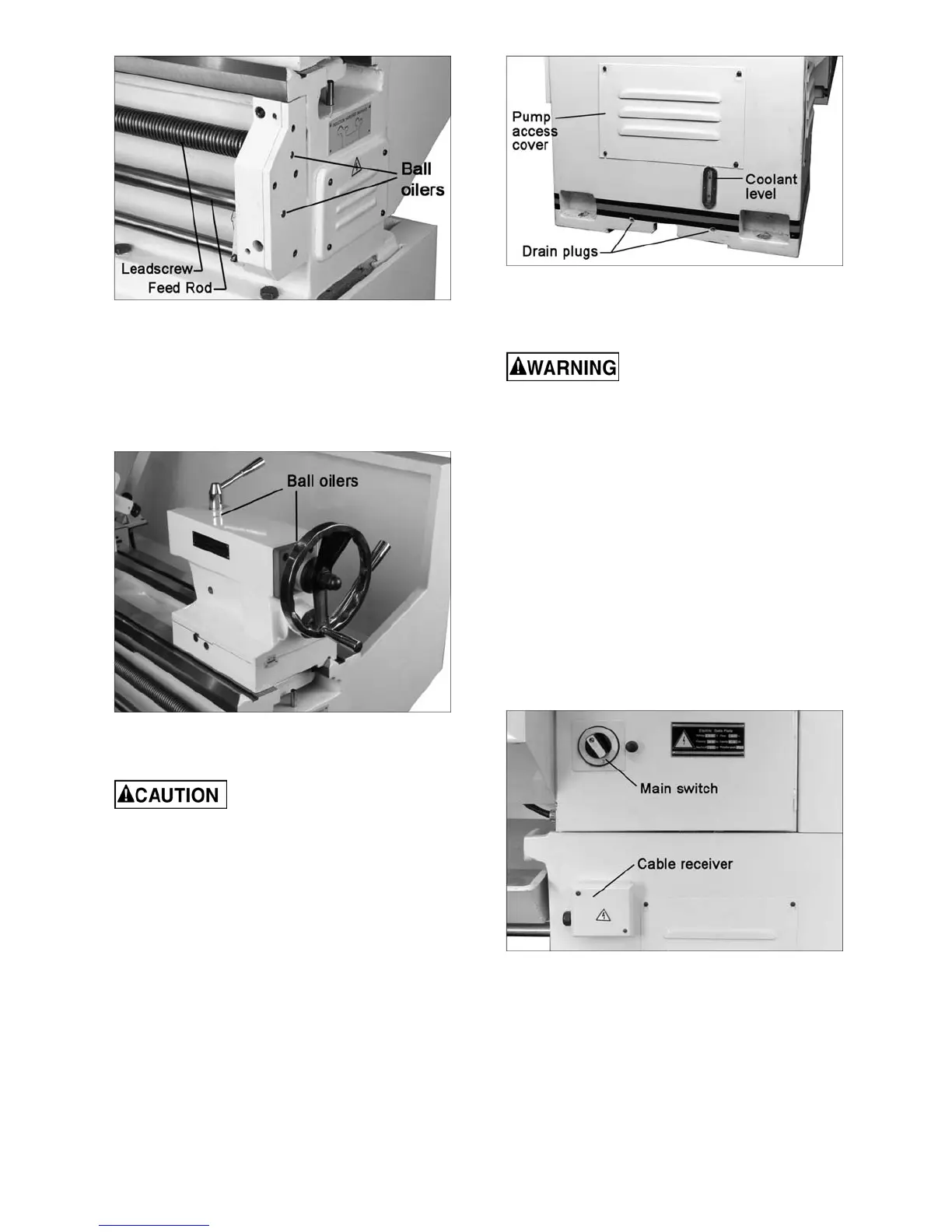
9.2 Coolant preparation
Follow local regulations
and/or coolant manufacturer’s recommend-
dations for use, care and disposal.
1. Remove access cover on the tailstock end of
the lathe stand (Figure 17). Make sure coolant
pump has not shifted during transport. Pour
four gallons (approximate) of coolant mix into
the reservoir. Use the gauge to determine
when full.
2. After machine has been connected to power,
turn on coolant pump and check to see that
coolant is cycling properly. Flow is controlled
by the tap at the base of the nozzle.
3. Reinstall access cover.
To drain coolant, remove two drain plugs (Figure
17).
Figure 17
10.0 Electrical connections
Electrical connections must
be made by a qualified electrician in
compliance with all relevant codes. This
machine must be properly grounded while in
use to help protect the operator from electrical
shock and possible fatal injury.
The main motor is rated for 230 volt only. Confirm
that power available at the lathe’s location is the
same rating as the lathe.
IMPORTANT: The lathe must be wired properly
and phased correctly. The spindle should rotate
counterclockwise (as viewed from the tailstock
end) while the feed rod rotates clockwise (as
viewed from the tailstock end). If the phasing
needs correction, disconnect lathe from power
source and switch any two of the three power leads
(not the green ground wire).
Make sure the lathe is properly grounded.
Figure 18 – Power input

 Loading...