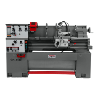
19
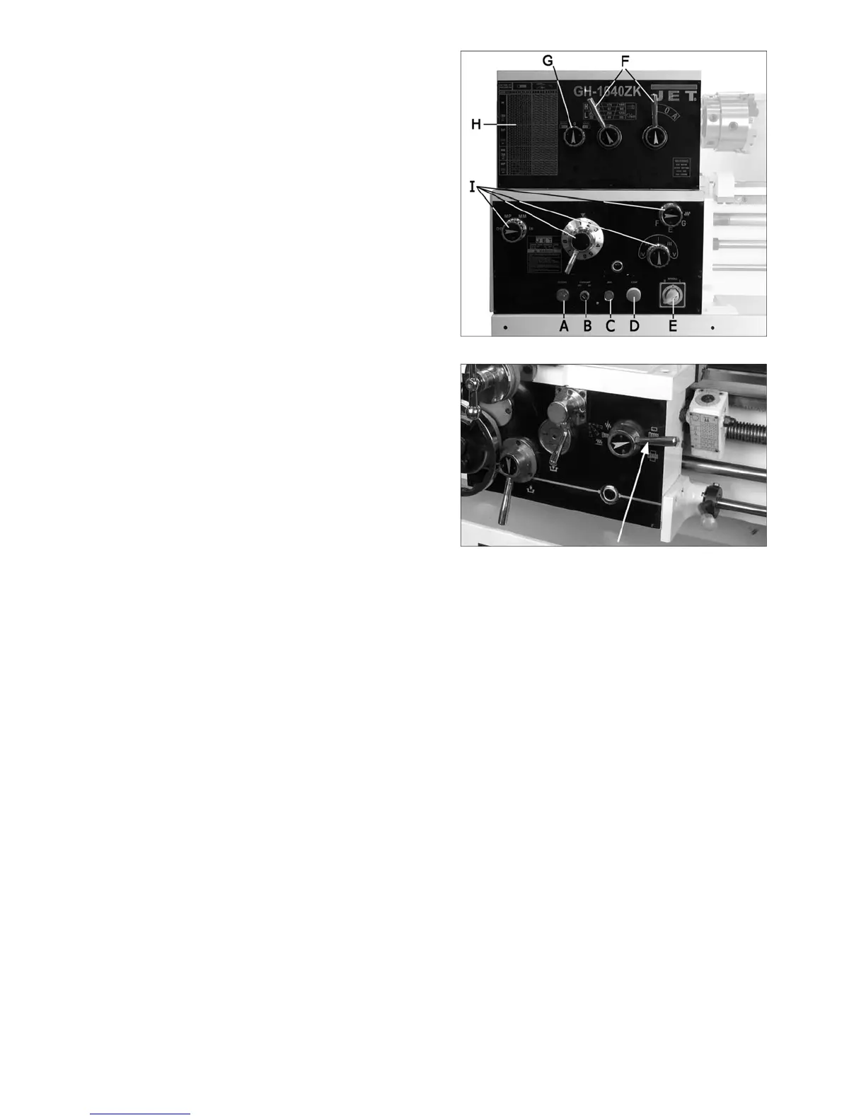
12.2 Spindle speed
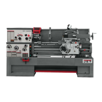
Twelve speeds are available by positioning the two
speed levers (F, Figure 27) according to the
accompanying chart on the front of the headstock.
You may need to turn the chuck by hand to assist
engagement of the gears.
Never change speed while spindle is turning.
12.3 Feed and thread selection
To obtain various feed settings and thread pitches,
the four levers (I, Figure 27) are used
conjunctively. Position the four levers according to
the Feed and Thread Chart on the front of the
headstock. The chart is also shown at the back of
this manual.
TIP: When selecting feed/speed correlations,
remember the general principal that high speeds
complement fine feeding, and low speeds are
better for coarse feeding.
12.4 Thread cutting
Threading is performed in multiple passes, with
decreasing depths in succeeding cuts. It is
recommended that test cuts be made on scrap
material and the results checked before proceeding
with regular material.
1. Move feed direction knob (G, Figure 27) to
desired direction, for right-hand or left-hand
threads.
2. Set speed levers (F
,
Figure 27) to desired
speed. Use lowest speed possible when
threading.
3. Select desired thread using thread pitch
levers (I, Figure 27) in conjunction with the
charts on the headstock. These charts are also
included at the back of this manual.
4. Set feed direction lever (see L, Figure 20) to
correct position (neutral).
5. Engage the half nut (M, Figure 20). The half
nut must be engaged during the entire
threading process when doing metric,
diametral, and modular threading.
6. When tool reaches end of cut, disengage and
back out the tool to clear the workpiece.
7. Reverse direction to allow cutting tool to return
to its starting point.
8. Repeat process until desired result is obtained.
Figure 27 – Operating Selections
Figure 28 – Half Nut Lever

 Loading...