Do you have a question about the Jet GH-1660ZX and is the answer not in the manual?
Understand all warnings on machine and manual for safety.
Remove jewelry, wear safety glasses, and appropriate clothing.
Maintain focus, use correct tools, and follow procedures.
Disconnect power for adjustments and cleaning.
Details what is covered, exclusions, and state law applicability.
Instructions on how to contact technical service for assistance.
Lists warranty durations for different product categories.
Detailed technical specifications for the 14-inch lathe model.
Detailed technical specifications for the 16-inch lathe model.
Detailed technical specifications for the 18-inch lathe model.
Detailed technical specifications for the 22-inch lathe model.
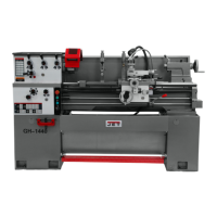
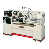
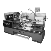
Details the bed and stand construction and mounted motor.
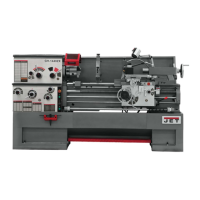
Explains the headstock, spindle, and included 3-jaw chuck.
Describes the carriage, apron, saddle, cross slide, and compound rest.
Covers tailstock, steady rest, and follow rest functions.
Describes foot brake, chuck guard, and work lamp.
Lists all items included in the lathe's shipping container.
Instructions for precisely leveling the lathe for accuracy.
Details cleaning protective surfaces and lubricating end gears.
Steps for preparing and installing the three-jaw chuck.
Recommendations for initial operation to ensure smooth break-in.
Procedures for checking and filling headstock and gearbox oil levels.
Steps for lubricating the apron and carriage components.
Lubrication for leadscrew, feed rod, and spindle direction controls.
Daily lubrication for key carriage and tailstock components.
Guidance on checking and adjusting V-belt tension.
Identifies and describes the main control panel components.
Explains headstock gear levers and feed/lead selectors.
Describes the leadscrew/feed rod directional dial and feed selectors.
Details handwheels, levers, and locks for carriage movement.
Explains tailstock adjustment levers and tool post clamping.
Covers tailstock offset, foot brake, micro carriage stop, and bed cover.
Table detailing inch feed rates and corresponding settings.
Tables for selecting settings for inch, metric, and diametral pitch threading.
Exploded view and parts list for the lathe stand.
Exploded view and parts list for the brake assembly.
Exploded view and parts list for the lathe bed.
Exploded views and parts lists for headstock components.
Exploded views and parts lists for change and quick change gear boxes.
Exploded views and parts lists for apron assemblies.
Exploded view and parts list for the carriage assembly.
Exploded views and parts lists for micro and carriage stops.
Exploded views and parts lists for tool post and tailstock.
Exploded views and parts lists for steady and follow rests.
Exploded view and parts list for coolant and work light.
Parts list and breakdown for the electrical cabinet and wiring.
Exploded view and parts list for safety guards and lubrication points.
Lists miscellaneous parts and accessories not covered in other assemblies.