17
adjustment is ever needed, follow the diagram
on the front of apron. Only qualified personnel
should make clutch adjustments.
12. Threading Dial (Q, Figure 20): Indicates the
point on the leadscrew where the half nut can
be re-engaged to continue inch threading.
13. Cross Slide Handwheel (R, Figure 20):
Located above the apron assembly. Clockwise
rotation moves the cross slide toward the rear
of machine. The accompanying scale is
graduated in 0.002 inch increments, and can
be calibrated by loosening the thumb screw
lock and rotating the ring as needed. Always
re-tighten ring before using the feed.
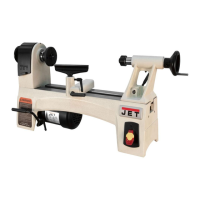
The cross slide lock is located at the right of
the cross slide (S, Figure 21).
14. Compound Rest: Located on top of the cross
slide and can be rotated 360° after loosening
the lock (T, Figure 21). There are calibrations
in degrees at the base of the rest to assist in
placement to the desired angle.
Figure 21
15. Compound Rest Handle (U, Figure 20):
Rotate clockwise or counterclockwise to
position. The accompanying scale on the collar
is graduated in 0.001 inch increments.
16. Tool Post Clamping Lever (V, Figure 20):
Rotate counterclockwise to loosen and
clockwise to tighten. Always use minimum of
two clamping screws to secure a cutting tool.
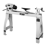
17. Tailstock Quill Clamping Lever (W, Figure
22): Rotate clockwise to lock the sleeve.
Rotate counterclockwise to unlock.
Figure 22 – Tailstock controls
18. Tailstock Clamping Lever (X, Figure 22): Lift
up to lock. Push down to unlock.
19. Tailstock Quill Traverse Handwheel (Y,
Figure 22): Rotate clockwise to advance the
quill and counterclockwise to retract it. Fully
retract it to eject a center or drill chuck.
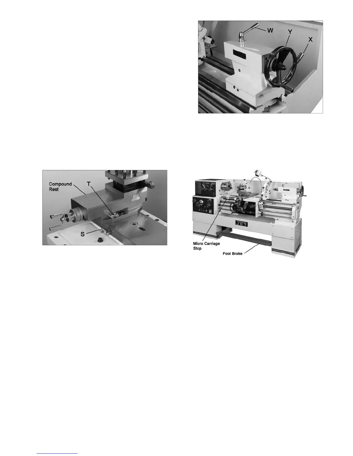
Figure 23 – Other controls
20. Foot Brake (Figure 23): For emergency
shutdown of all lathe functions. The connecting
rod mechanism is in the bed stand, and
activates a brake strap at the main motor.
(Caution: Lathe still has power.) The foot
brake is not intended for normal stopping of
the lathe. Overuse can result in hastened wear
of brake parts.
21. Micro Carriage Stop (Figure 23): Can be
used during manual feed operation to limit
carriage travel. NOTE: It is not intended to
stop the carriage during automatic feed. The
carriage stop can be repositioned along the
bed by loosening the two screws underneath
the stop.

 Loading...