Operation Manual
Total 21
page 4
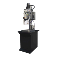
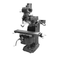
2.1 For the machine appearance and its main technical data, see diagram 1 and table 1.
3. Brief description of the driving system and its structure:
The machine consists of spindle box, column, machine base, electric cabinet and machine
accessories, total five component parts. Spindle revolution is main motion of the machine.
During drilling and milling processing, spindle movement along with its axis is a feed motion.
Spindle box up and down movement is an auxiliary motion.
Two operating levers in the front of spindle box could make changes for the spindle speed in
12 steps. Changing either lever position could drive a triple gear and a double gear moving
along with axis direction results the speed change. One of levers has an idle position that is
for the spindle rotation by manual for loading and unloading of tool cutters as well as for the
adjustment of work piece only.
Up and down movement of the spindle box is completed by manual, Adjustment for the
required distance of cutter and work piece could also be made by manual.
Please refer to the diagram 2 for the transmission system of the machine.
For the gear, worm and worm shaft, rack and pinion etc, please see table 1.
For the details of roller bears to be used on the machine, please refer to the diagram 3 and for
a list of roller bears, please refer to the table 2.
4. Electrical system
4.1 Brief description
The machine is suitable for the power supply for 400V/50HZ 3 phase. Special voltage with
60HZ could also be available as per the requirements of the end user.
4.2 Explanation of the circuit(refer to drawing4、5)
The spindle of the machine is moving by two-speed motor, it is controlled by switch(QSA1)
AC contactors (KM1) and so on.
When using the machine, the breaker QF1, fuse FU1,FU2,FU3 which is in the electrical
Box B1 must be put on, when examining and repairing, it could be put off. The spindle motor
and pump motor use breaker and fuses for his protection, and the switch features overload
protection, short cut protection and phase break protection. Press the main power switch
QS1,the electrical source HL1 light up, it is working now, contrary, work is stopped.