EasyManua.ls Logo

Jet J-4300A User Manual

Default Icon
36 pages
To Next Page IconTo Next Page
Page #1 background imageLoading...
Page #1 background image
Operating Instructions and Parts Manual
Disc, Belt and Combination Disc/Belt Sanders
Models: J-4200A J-4300A J-4400A
J-4200A-2 J-4301A J-4401A
J-4202A
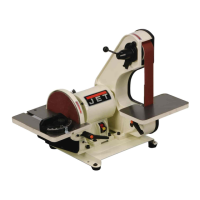
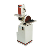
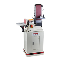
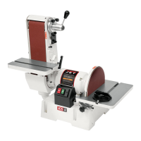
J-4200A Disc/Belt Sander J-4300A Belt Sander J-4400A Disc Sander
JET
427 New Sanford Road
LaVergne, Tennessee 37086 Part No. M-414551
Ph.: 800-274-6848 Revision C1 01/2014
www.jettools.com Copyright © 2014 JET

Table of Contents

Questions and Answers:

Jet J-4300A Specifications

General IconGeneral
TypeBelt and Disc Sander
Motor Power1/2 HP
Dust CollectionYes
Weight44 lb
Belt Speed3100 SFPM
Disc Diameter6 inches
Belt Size4 x 36 inches

Summary

1.0 Warranty and Service

Warranty Period Overview

General warranty duration and product-specific limited warranties.

What the Warranty Covers

Defects in workmanship/materials, subject to limitations.

Getting Technical Support

Contacting technical service for assistance and Authorized Service Centers.

Warranty Limitations and Exclusions

Exclusion of implied warranties and liability for damages.

Product Warranty Chart

Chart detailing warranty periods for different product categories.

3.0 Safety Warnings

General Safety Cautions

Misuse can cause injury; proper setup, use, and service are critical.

Machine Setup Safety

Precautions for machine setup: work area, anchoring, guards, switch.

Machine Operation Safety

Precautions during operation: guards, apparel, overreaching, unattended use.

Machine Servicing Safety

Precautions during maintenance: power disconnection, manual adherence.

General Machinery Safety Guidelines

Specific safety advice for operating machinery.

Electrical Safety Precautions

Grounding requirements and qualified electrician for electrical work.

Abrasive Sanding Machine Safety

Safety measures for abrasive sanding operations.

4.0 Machine and Manual Overview

5.0 Specifications

6.0 Operating Instructions

6.1 Belt Sander Operation

Importance of belt condition, tension, and tracking.

6.2 Adjusting the Belt Sander Table

How to tilt the belt sander table.

6.3 Indexing Lock Handle Use

Repositioning the belt table locking handle.

6.4 Adjusting the Belt Sander Arm

Adjusting the belt sander arm to vertical or horizontal.

6.5 Adjusting the Disc Sander Table

How to adjust the disc sander table angle.

6.6 Using the Miter Gauge

Using the miter gauge for sanding angles.

7.0 Maintenance

7.1 Belt Replacement Procedure

Step-by-step guide for replacing the sanding belt.

7.2 Track Mechanism Maintenance

Cleaning and maintaining the belt tracking mechanism.

7.3 Installing Abrasive Discs

Procedure for installing new abrasive discs.

7.4 Replacing the V-Belt

Steps to replace the machine's v-belt.

8.0 Machine Setup

8.1 Basic Setup Procedures

Positioning, anchoring, and electrical connection.

8.2 Disc Table Angle Adjustment

Setting the disc table to a 90° angle.

8.3 Disc Table Miter Parallelism

Aligning the disc table parallel to the miter slot.

8.4 Disc Table Gap Adjustment

Adjusting the gap between the disc table and disc.

8.5 Belt Table Miter Slot Parallelism

Aligning belt table parallel to miter slot.

8.6 Belt Table Angle Adjustment

Adjusting the belt table angle.

8.7 Adjusting or Replacing the Platen

Adjusting or replacing the platen for belt sanding.

9.0 Electrical Connections

9.1 Single Phase Electrical Hookup

Connecting single-phase power to the machine.

9.2 Three Phase Electrical Hookup

Connecting three-phase power to the machine.

10.0 Troubleshooting

11.0 Replacement Parts

Model J-4200A Assembly Diagrams and Parts

Exploded view and parts list for J-4200A belt/disc sander.

Model J-4300A Assembly Diagrams and Parts

Exploded view and parts list for J-4300A belt sander.

Model J-4400A Assembly Diagrams and Parts

Exploded view and parts list for J-4400A disc sander.

Base Assembly Diagrams and Parts

Exploded views and parts lists for various base assemblies.

12.1 Electrical Schematic - Single Phase

12.2 Electrical Schematic - 3 Phase

Related product manuals