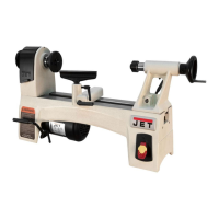
Nomenclature and Use
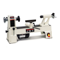
Spur Center (A, Fig. 2) - locks into headstock
and holds the workpiece during spindle turning.
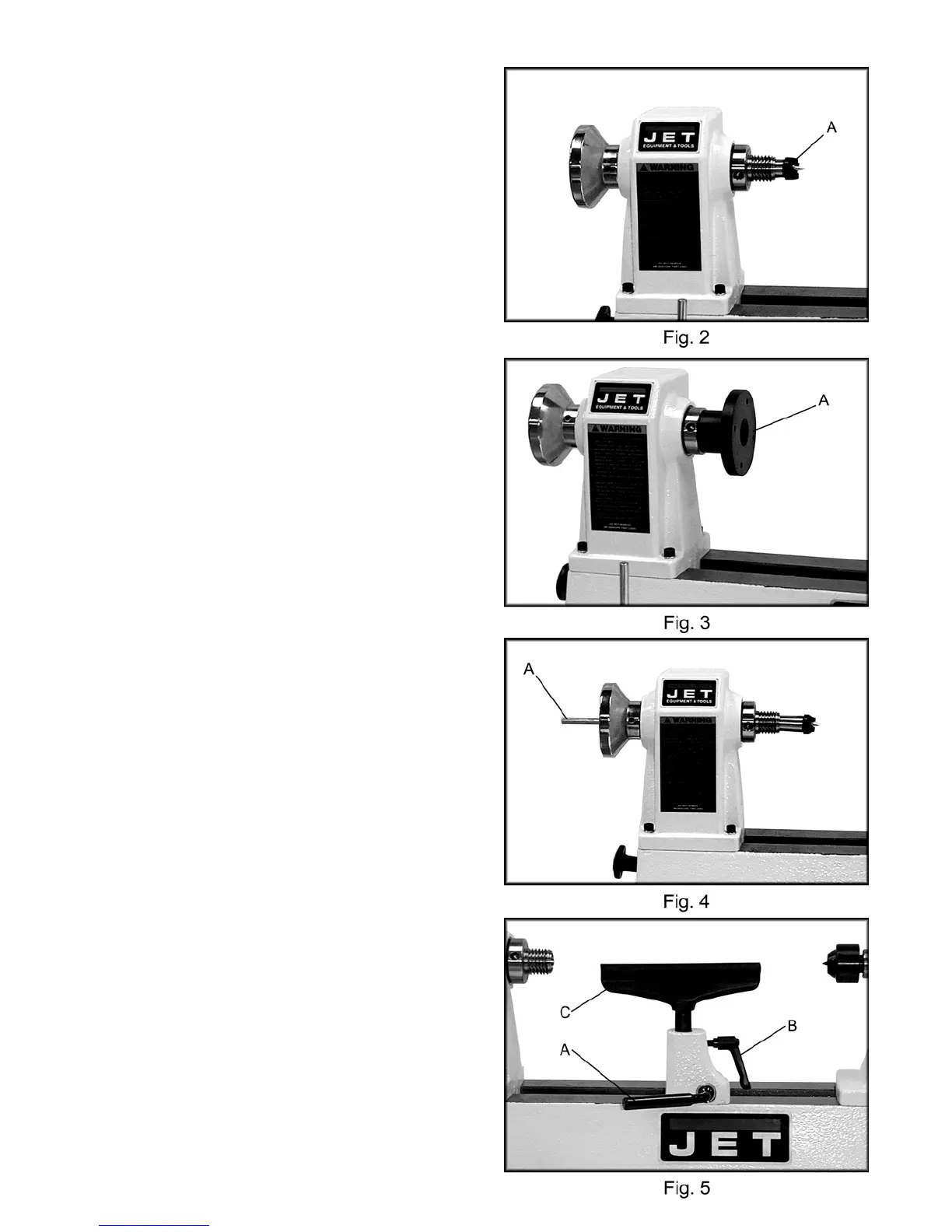
Face Plate (A, Fig. 3) - attaches to headstock
and is used in face plate turning operations.
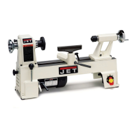
Drift Rod (A, Fig. 4) - slides into the headstock
to tap the spur center free. Stored in the hole in
the base below the headstock.
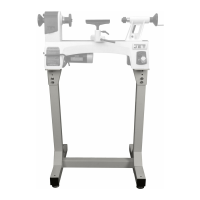
Tool Rest (Fig. 5) - attaches to the bed. Used
to steady cutting tool during spindle turning or
face plate operations.
Adjusting the Tool Rest
Position the tool rest as close to the work piece
as possible. It should be 1/8" above the
centerline of the work piece.
Position the tool rest base on the bed by
releasing the lock handle (A, Fig. 5) and sliding
onto the desired position. Tighten handle (A,
Fig. 5) to lock. Adjust the height of the tool rest
by loosening handle (B, Fig. 5) and raising arm
(C, Fig. 5).
Should adjustment of the tool rest clamping
device become necessary, turn off the machine,
reach under the bed, and adjust the clamping
nut.