Fig 5
You can now position the belt in the
desired speed range.
Note:
The “High” speed range (1700-3900)
provides maximum speed, where as
the “Low” speed range (500-1200)
will provide maximum torque.
Close and lock the belt covers.
7.2 Adjusting tool rest
Position the tool rest (C, Fig 6) as
close to the workpiece as possible.
Tighten handle (A) to lock.
Fig 5
Set the height to appr. 3mm above
centre. Tighten indexable knob (B).
7.3 Installing work holding
Disconnect the machine from the
power source (unplug)
The face plate (A, Fig 7) screws on
the spindle nose thread.
Fig 7
Mount the workpiece directly to the
face plate using 4 brass wood screws
from the back. Be careful to use
screws short enough not to interfere
with the cutting process but long
enough to hold the workpiece securely
to the face plate.
If screw mounting is not allowed at all,
the work may be glued to a backing
block and the backing block screwed
to the face plate. A piece of paper in
the glue joint will prevent damaging
the wood when separated later.
Mount the face plate with the
workpiece already attached onto the
spindle nose thread and hand tighten.
Turn the workpiece by hand to see if it
rests securely and can be rotated
freely.
For face plate turning the tool rest is
set slightly lower than centreline.
Caution: always cut with your chisel
on the left half of the workpiece only.
The spur drive centre (A, Fig 8) locks
into the spindle taper and can be
removed with the knockout rod (B).
Fig 8
Mount the workpiece between the spur
drive and the tailstock live centre.
Turn the tailstock hand wheel until the
live centre well penetrates the
workpiece. Reverse the hand wheel by
one quarter turn and lock the tailstock
spindle.
Turn the workpiece by hand to see if it
rests securely between centres and
can be rotated freely.
For turning between centres the tool
rest is set appr. 3mm higher than
centreline.
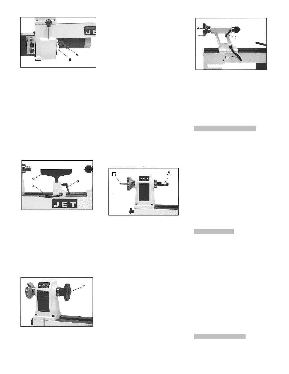
7.4 Adjusting tailstock
Turn the hand wheel (A, Fig 9)
clockwise to move tailstock spindle
forward. Lock spindle with the
indexable knob (B).
Fig 9
The handle (C) locks the tailstock in
position on the bed.
The live centre can be ejected by
turning the hand wheel counter-
clockwise.
The live centre pin can be removed to
allow deep hole drilling operations.
8. Maintenance and inspection
General notes:
Maintenance, cleaning and repair
work may only be carried out after
the machine is protected against
accidental starting by pulling the
mains plug.
Clean the machine regularly.
Inspect the proper function of the dust
collection daily.
Defective safety devices must be
replaces immediately.
Repair and maintenance work on the
electrical system may only be carried
out by a qualified electrician.
9. Trouble shooting
Motor doesn’t start
*No electricity-
check mains and fuse.
*Defective switch, motor or cord-
consult an electrician.
*Overload has reacted-
-Turn off machine power
-Push the reset button
-Then re-start the lathe.
Machine vibrates excessively
*Stand on uneven floor-
adjust stand for even support.
*Workpiece is not properly centred-
*The speed is too high-
10. Available accessories
 Loading...