9
The planer should be operated in a well-lit area with
good ventilation.
Exposed metal surfaces, such as tables, rollers,
cutterhead, etc., may have been given a protective
coating at the factory. This can be removed with a
soft cloth moistened with a good commercial
solvent. Do not use acetone, gasoline, lacquer
thinner, or other solvents with a low flash point. Do
not use an abrasive pad because it may scratch
metal surfaces.
Use care when cleaning around
cutterhead area; knives are extremely sharp.
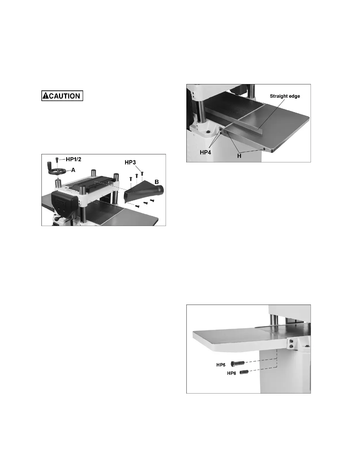
5.4 Handwheel
Install handwheel (A) onto shaft, making sure to
orient it with the flat on the shaft. Insert socket hd
cap screw with lock washer (HP1,HP2) and tighten.
See Figure 5-3.
Figure 5-3: handwheel and dust port
5.5 Dust Port
Mount dust port (B) to rear of head casting with six
button head screws (HP3). See Figure 5-3.
It is strongly recommended that you use a dust
collection system (not provided) with this planer.
Connect a 4-inch dust hose to the port and secure
with a hose clamp. Visit JET’s website or contact
your dealer for a complete line of dust collectors.
IMPORTANT: If you are not using a dust collection
system, do not attach the dust port to the planer, as
the accumulation of dust inside the port may create
a safety hazard, or eventually cause jamming of the
rollers.
5.6 Extension tables
The JWP-15B is shipped with steel tables. The
JWP-15BHH is shipped with cast iron tables.
JWP-15B only:
1. Mount the steel extensions to the main table
using the screws provided (HP4, Figure 8-9).
The bottom screw is used as a stop. The
extension table pivots on the top screw.
2. The extension tables must be leveled with the
main table. A straight steel bar is ideal for this,
but a carefully jointed board may also be used.
Place the straight edge across extension table
and main table, as shown in Figure 5-4. Move
the straight edge to different places along the
table width during the alignment process.
3. Loosen screws (H) with provided Torx point
screwdriver and adjust table up or down at each
of the four corners as needed until straight edge
sits flush across both tables at all points.
Tighten screws (H).
Figure 5-4: extension tables (JWP-15B only)
JWP-15BHH only:
1. Insert 3 set screws (HP6, Figure 5-5) into the
lower holes of a cast iron extension table.
2. Mount the extension table with three hex cap
screws (HP5) using a 13mm wrench. Do not
fully tighten yet.
3. Place a straight edge (straight steel bar or
carefully jointed board) across extension table
and main table, as shown in Figure 5-4.
4. Adjust extension table until it is even with main
table, and snug the screws (HP5) a little more.
Then turn any of the 3 set screws in or out as
needed until straight edge sits flush with
extension table and main table at various points
along their width.
5. Tighten hex cap screws (HP5).
6. Repeat for opposite extension table.
Figure 5-5: extension tables (JWP-15BHH only)