computer radio control system
EN
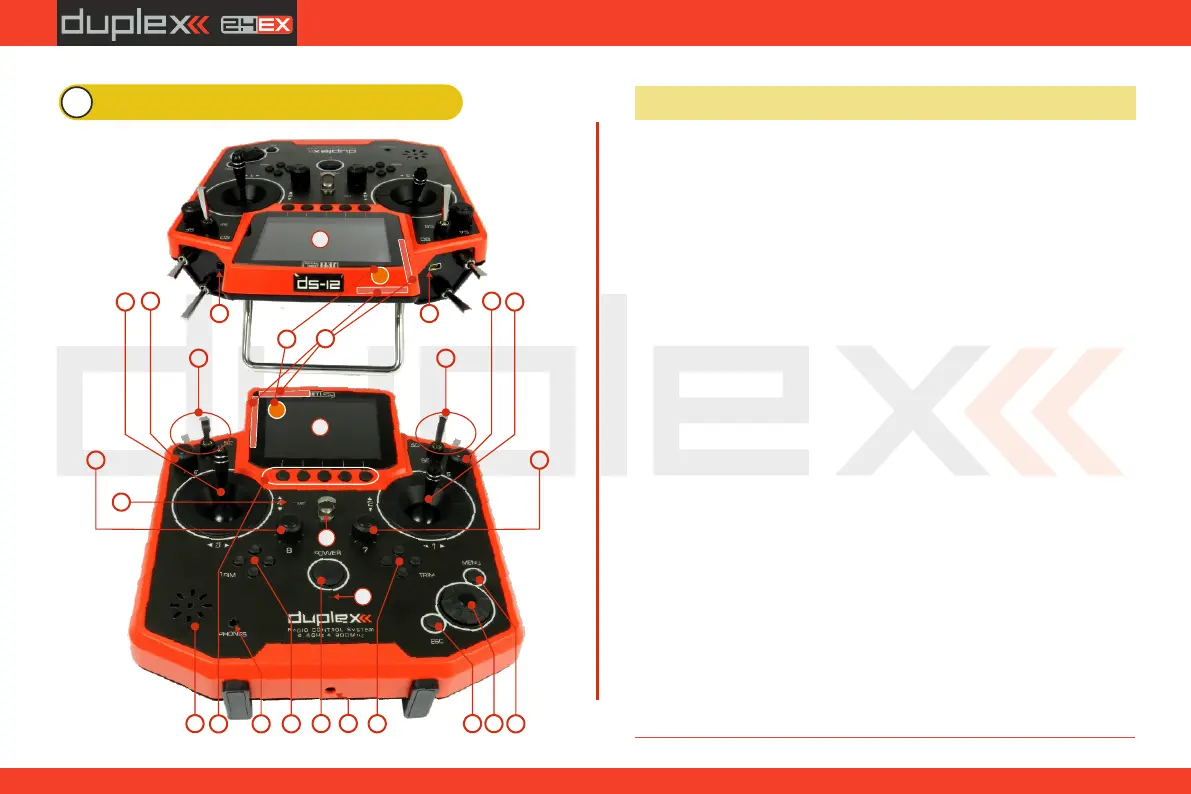
4 Description of Transmitter DS-12
1. Right Stick 1, 2 – the DS-12 Transmitter Supports Modes 1-4, see Control
Sticks -> mode change
2. Left Stick 3, 4 the DS-12 Transmitter Supports Modes 1-4, see Control
Sticks -> mode change
3. Swappable and Assignable Switches: Sa, Sb, Sc, Sd, Se, Sf
4. Digital Trims for the Left Stick T3, T4
5. Digital Trims for the Right Stick T1, T2
6. Right Rotary Control Knob 5
7. Left Rotary Control Knob 6
8. Rotary Control Knob 7
9. Rotary Control Knob 8
10. LCD Display
11. Function Buttons F1 – F5
12. Transmitter On/Off Power Switch
13. 3D Control Selector
14. Menu Button
15. ESC Button
16. Shows the 2.4GHz Antenna but NOT the handle.
17. Charge Jack
18. USB PC Interface
19. PPM Input/Output
20. ON/OFF & Charging LED Indicators
21. Speaker
22. Neckstrap Hook
23. Earphone Jack
24. 900 MHz Antenna
25. Microphone
4.1 Control Identification DS-12
3
4
5
7
8
12
13
15
14
16
17
18
21
2
1
3
6
9
11
19
22
23
24
20
25
10
10
15