9629 Microprocessor Controller
- 30 -
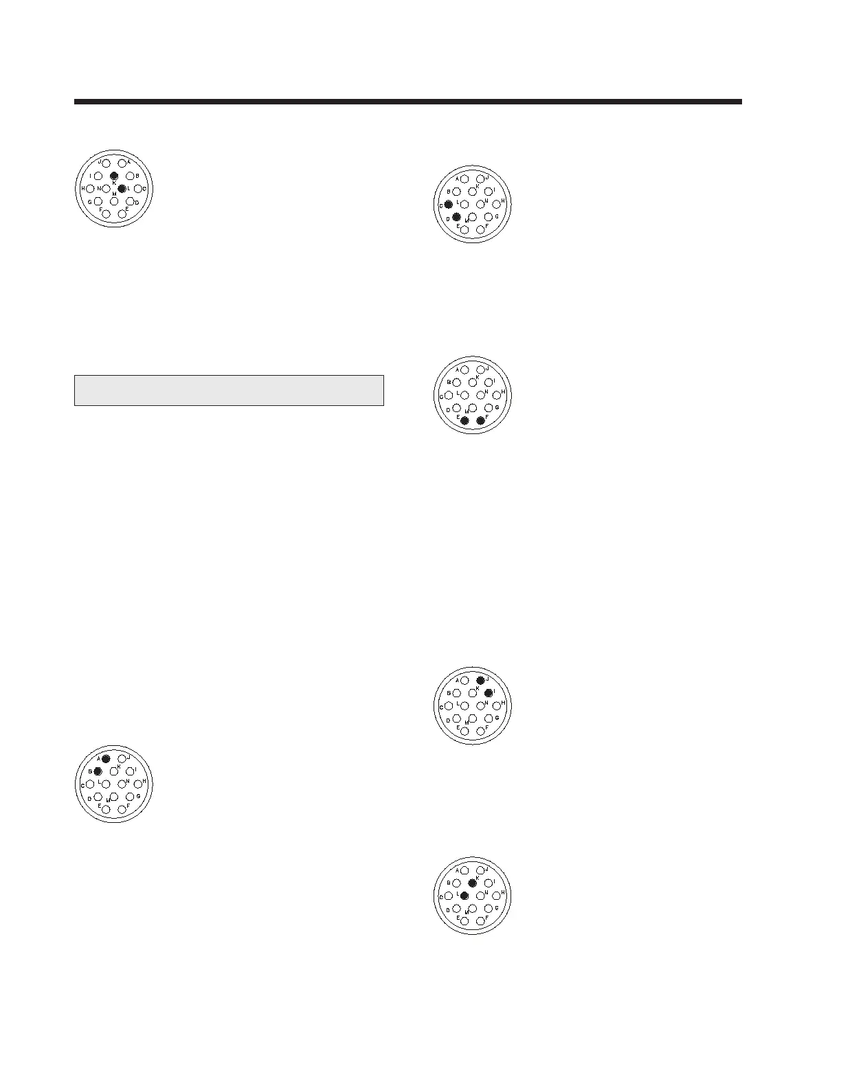
PULSE LOCKOUT OUTPUT (Pins K & L)
Function: Permits the 9629 to pass
a pulse signal to another device.
This signal would be used if it is
desired to send a pulse lockout
signal to an arc length control or
a third party control. The signal from these
pins directly follows the Pulse Lockout Input
signal.
Electrical: This is an open collector output, Pin
K is high, Pin L is low.
S2 CONNECTOR
The S2 connector is used to connect the 9629
control to a 9627 carriage control or to a 9640
circumferential xture control. In certain cir-
cumstances, it can be interfaced with a PLC,
power supply or other control interface. Jetline
can provide standard connecting cables to be
connected to the S2 connector on the 9629 con-
trol. If you need to provide your own cable, it
should be tted with the following:
Amphenol plug 3106A-20-27P
Cord Grip 97-3057-1012-1
Pin Connection Details
Connections should be made as shown below.
Note: Pins G, H, M and N are reserved.
REMOTE START INPUT (Pins A & B)
Function: When this circuit is
completed, the 9629 control will
start the feeding of the wire.
Electrical: You can connect a dry
relay contact or an open collector signal, Pin A
is high, Pin B is low. Either one must handle
12VDC at 4mA. This must be a maintained
contact, removing the contact closure will be
treated as a stop signal.
REMOTE EMERGENCY STOP INPUT
(Pins C & D)
Function: When this circuit is
opened, the 9629 control will initi-
ate an emergency stop sequence.
Electrical: You can connect a dry
relay contact or an open collector signal, Pin C
is high, Pin D is low. Either one must handle
12VDC at 4mA. Logic must be normally
closed.
PULSE LOCKOUT INPUT (Pins E & F)
Function: When the control is
connected to a power supply with
pulsed current facilities, it is some-
times desirable to synchronize arc
length control with the current pulsing. When
the 9629 control is connected to the current
background signal through these connections, it
will allow a signal to be passed to the arc length
control. These pins accept the same input as Pins
E and F on connector S1.
Electrical: You can connect a dry relay contact
or an open collector signal, Pin E is high, Pin F is
low. Either one must handle12VDC at 4mA.
REMOTE EMERGENCY STOP OUTPUT
CONTACT (Pins I & J)
Function:
When the emergency
stop button is pressed, this contact
will open. This will prohibit the
operation of an ancilliary control (if
one is connected).
Electrical: We supply a dry relay contact ca-
pable of handling 110VAC at 0.6A.
PULSE LOCKOUT OUTPUT (Pins K & L)
(Alternative connection - see S1, pins K & L and interconnection diagrams)
Function: Permits the 9629 to pass
a pulse signal to another device, i.e.
an arc length control. The signal
from these pins directly follows the
Pulse Lockout Input signal.
Electrical: This is an open collector output, Pin
K is high, Pin L is low.
 Loading...