9629 Microprocessor Controller
- 28 -
Section VIII.
Mechanical Installation
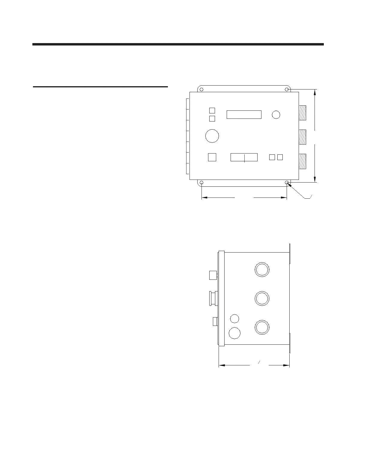
The 9629 control is mounted in a steel enclosure
with a hinged front panel to facilitate servicing.
The front panel consists of a polycarbonate
overlay with tactile switches and integrated
touch pads.
Three Amphenol connectors are located on the
right side of the enclosure, the fuse is located
on this side and the power cord exits from this
side. When planning the location of the control,
sufcient access for the connections should be
provided at the right hand side of the unit, we
recommend allowing a space not less than 5”
(125 mm).
The front panel is hinged for servicing purposes.
The hinge is located at the left hand side of the
enclosure so it is important that you do not lo-
cate the 9629 too close to an obstruction on the
left side which would block the full opening of
the door.
Plates are provided on the rear of the enclosure
with four mounting holes, two at the top and two
at the bottom. The location and size of these
holes is shown on the drawing on the right side
of this page. Use ¼” (6 mm) diameter screws to
secure the control to the mounting face.
We recommend that the control should be
mounted so that front panel is vertical or slopes
back at an angle of no more than 30° from the
vertical. There is, in theory, no problem in
mounting the control in any orientation, but the
vertical or slightly sloping front panel position
will prove to be best for the operator.
Because the control includes a digital display,
the best location will be where the display is
close to eye height from the oor. The vertical
front panel orientation will also ensure that the
LCD display is clearly visible - avoid a loca-
tion where very bright light falls on the display,
this will cause a reection from the transparent
overlay and make it difcult to clearly read the
display.
16” Dia
(8mm)
5
FRONT VIEW
SIDE VIEW
(Right Hand Side)
S1
S3
S2
8”
(200mm)
8 ¾”
(222mm)
1
6
8”
(156mm)
 Loading...