length control operate automatically to provide coordinated start of the various parameters. At the
end of the weld, operation of the 9700T stop push-button initiates a controlled end of weld sequence
with downslope and wire and travel stop delays.
Required Connections and Cables showing old and new versions
:
9627 9700T
S1: 9627/9700T to welding power supply.
Cable: 9600S1-DX10-15 (For Miller)
Change to 9700S1-MLR28-15
S2: 9627/9700T to 9629/9700W control
Cable: 9600S2-S2-3
Change 9700S2-S2-3
S3: 9627/9700T to carriage drive motor.
Cable: Included with carriage
9629 9700W
S1: 9629/9700W to arc length control
Cable: 9600S2-ALC-3
Change to 9700S1-ALC74
S2: 9629/9700W to 9627/9700T control
Cable: 9600S2-S2-3 (same cable as above)
Change 9700S2-S2-3
S3: 9629/9700W to wire drive motor
Cable: Included with wire feed head
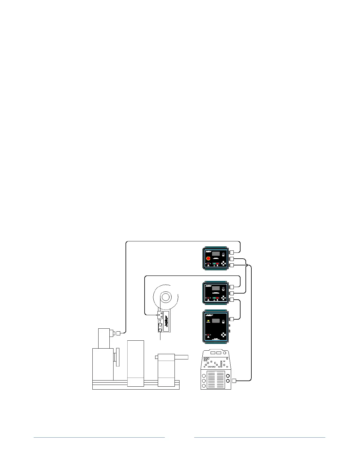
Figure 7: Typical Jetline System Interconnection Schematic for a GTAW with Wire feeder and Motion
Control. NOTE: Fixture shown is rotation but connection same for linear.
Welding Power
Source Remote
Connection