9
Fire Battery Connection and Fitting
The battery at the fire is a special battery pack 2xD, 7.2 volts sealed long life Lithium (Fig. 5b)
The battery should be located underneath the burner on the left hand side of the fire.
Pull the battery lead (red and black) forward out to the front of the fire and carefully connect the
plastic connector to the plastic connector situated on the lead attached to the battery. Ensure that
the connector is correctly connected.
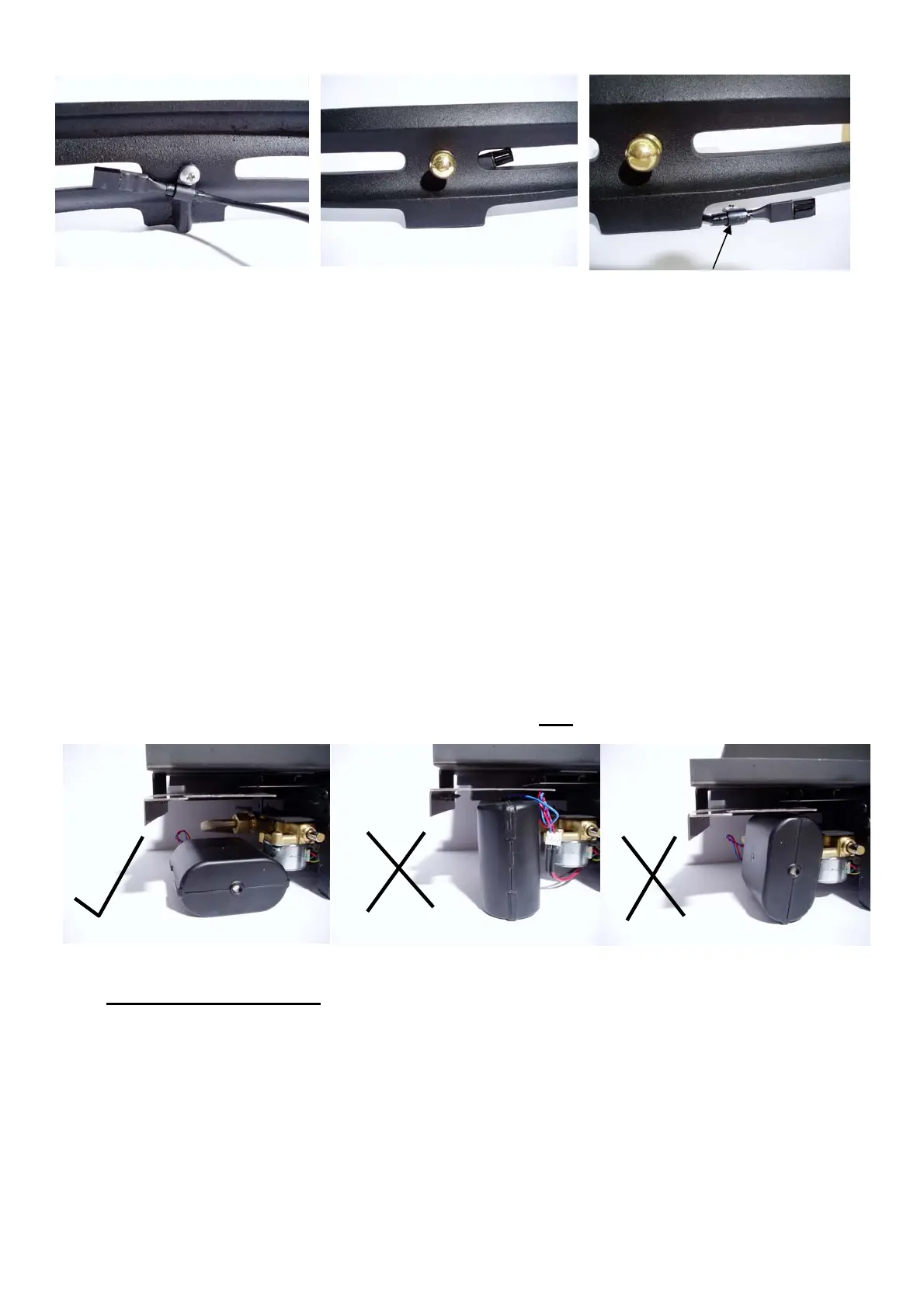
Fit the battery under the burner ensuring that the battery lead is facing downwards and away from
the underside of the burner. (To prevent the lead from touching a hot surface).
The battery should sit on the recess floor / hearth as far forward and left as possible just behind the
fire front. This allows for easy battery replacement. (See section Changing the batteries Remote
Control page 21).
The fire battery must be laid flat underneath the burner not on its side edge or upright
Battery Position Correct Battery Position Incorrect Battery Position Incorrect
Gas Connection
A means of isolation must be provided in the supply to facilitate servicing. An 8mm compression
isolating cock/pressure test point has been supplied at the inlet to the appliance. This is required to
allow subsequent servicing to take place.
The gas connection can be made left hand or right hand. A right hand connection is recommended.
Refit the burner tray and complete the gas connection by connecting the pipe to the isolating cock/
pressure test point elbow. Turn the gas supply ON and check for gas soundness at all joints.
Open Front shows P clip
attached to rear of ash pan
cover using ash pan knob
screw. Sensor must be
visible through slot as
shown in fig 5f
Shiny side of sensor must
be visible through slot.
Fig. 5e Fig. 5f
Sensor mounted to hearth with
P clip. Alternatively sensor can
be mounted to centre of ash
pan cover using double sided
tape. See fig 5d
Fig. 5g
P clip and screw
Fig 6