22 23
18-R001/EN_FACTORY GP_part B
18-R001/EN_FACTORY GP_part B
5
7
4
6
1
2
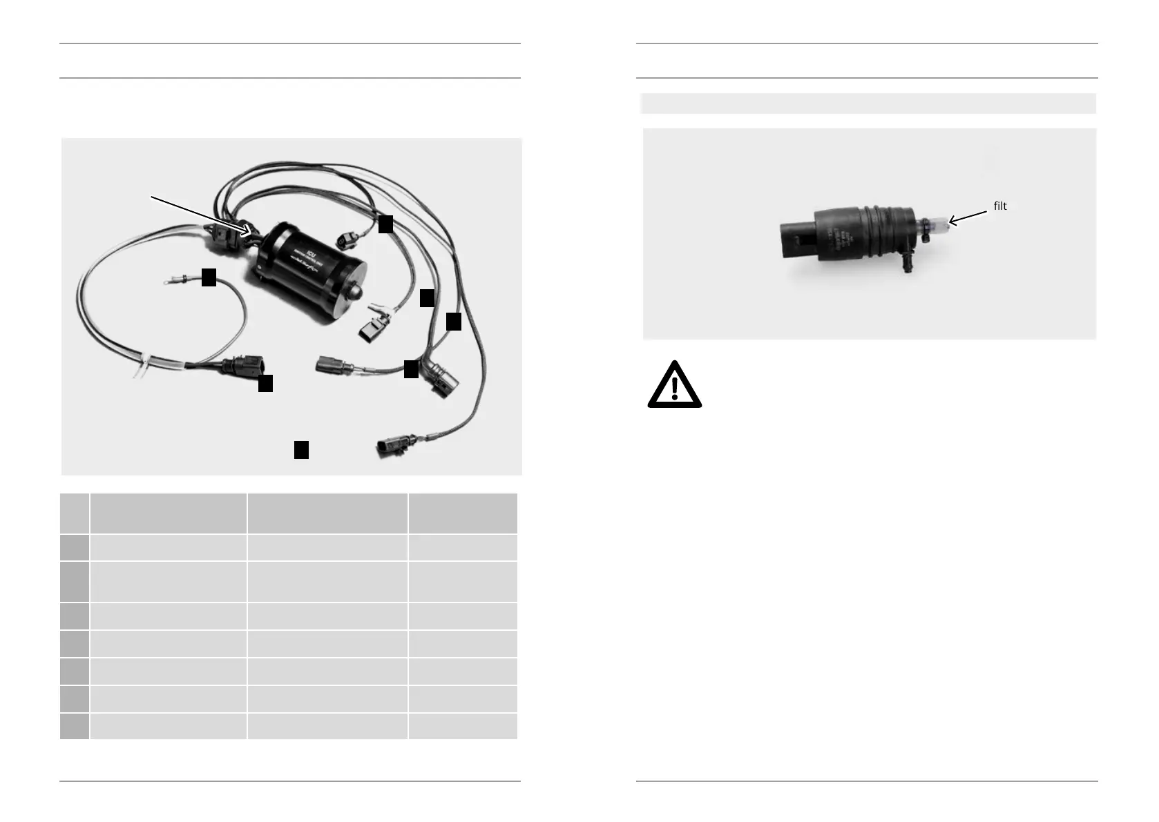
The ignition control unit (ICU) is connected with the other components using these cables.
The numbers of the positions in the table correspond to the numbers in the following gure:
Posi-
tion
Connector type Connector colour Device
1 2-pin female Red (+), black (-) Starter
2 Cable eye Black with the yellow and
green end
Ground cable
3 3-pin male Red (+), black (-), white (c) Control handle
4 2-pin male Orange (+), black (-) Ignition coil
5 4-pin female Red, white, blue, black Charging
6 2-pin female Yellow (+), black (-) Electric bilge pump
7 3-pin female Red (+), black (-), white (sig) Timing sensor
DESCRIPTION DESCRIPTION
3
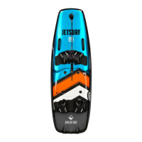
ELECTRIC BILGE PUMP
Please check the function of the bilge pumps before every ride and du-
ring the ride.
Keep the suction lters clean.
The bilge pumps suck water from the internal area of JetSurf. They are a vital part for the JetSurf
operation. During every ride, check whether the pumps work properly.
WARNING
lter
central connector