24 25
18-R001/EN_FACTORY GP_part B
18-R001/EN_FACTORY GP_part B
PROCEDURE OF IDLE SETTING
Required tools: Allen key 2.5 (spanner No 8 for the back nut)
Note 1: Freewheel screw – position 1 – it is secured with a back nut from below. If you adjust
the freewheel, FIRST LOOSEN THIS NUT. When the freewheel has been set, retighten it.
The freewheel must be set at the operating speed of the engine (the engine should be running for
some time).
The screw for setting the freewheel revolutions (position 1) is set by the manufacturer in such
a way that the engine keeps running for a while by itself when started on land (without requiring any
throttle control).
If the engine stops by itself, it is necessary to tighten the freewheel screw (position 1) to the right
by half a turn. Tightening can be repeated as required.
If the engine revolutions are too high (it does not switch o in the freewheel), the freewheel screw has
to be loosened by turning to the left.
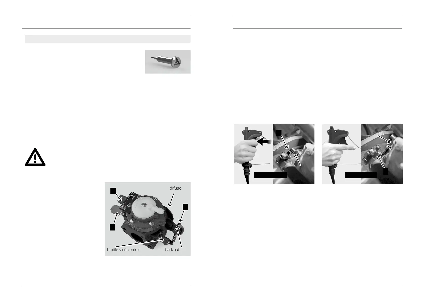
Note 2: When setting the freewheel, also check both extreme positions of the throttle shaft control.
Step 1: If the throttle trigger on the control handle is in the extreme position (pressed), the throttle
shaft control must be in position A – FIGURE 1. Step 2: If the throttle trigger is in the other extre-
me position (released), the throttle shaft control must be in position B – FIGURE 2.
A
B
CARBURETTOR
CARBURETTOR ADJUSTMENTS
Replacement or repair of any emission related component must
be executed in a manner that maintains emission levels within the
prescribed certication standards.
JetSurf motorized surfboards are certied to the United States En-
vironmental Protection Agency (EPA) as conforming to the require-
ments of the regulations for the control of air pollution from new watercraft engines. This certica-
tion is contingent on certain adjustments being set to factory standards. §1068.101(b)(1) prohibits
tampering, removal or rendering inoperative any device installed onto the engine in compliance
with EPA regulations prior to sale and delivery to, as well as after the sale to, the ultimate purchaser
of the product.
Dealers are not to modify the engine in any manner that would alter the horsepower or allow emi-
ssion levels to exceed their predetermined factory specications.
Tamper proof provisions: The carburetor is equipped with tamper proof screws – see below. For
changing the adjustment the special tool is required (custom design). There is also applied glue on
the screw to prevent adjustment by the pliers for example. When the glue is broken, it is a proof
of unauthorized settings.
IF THE CARBURETTOR SETTING IS INTERFERED WITH BY A PERSON
WITHOUT THE REQUIRED TECHNICAL KNOWLEDGE, IT CAN RESULT IN
POOR ENGINE OPERATION AND ITS DAMAGE. THIS DAMAGE IS NOT CO-
VERED BY THE WARRANTY.
The carburettor is a vital part of the
engine and it requires highly sophisti-
cated adjustments.
The carburettor has three basic adjusting
screws:
1 – A screw for adjusting the freewheel
revolutions (a freewheel screw)
2 – A screw of the freewheel jet L
3 – A screw of the main jet H
Screw adjustment – positions 2 and 3
are ALWAYS to be left to the seller.
NOTICE
difusor
throttle shaft control back nut
3
2
1
FIGURE 1 FIGURE 2
throttle
shaft
control
throttle
shaft
control
DESCRIPTION DESCRIPTION