13
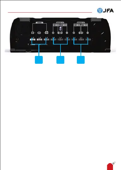
1 Power connection: Connect the positive (+) terminal directly to
the positive pole of the batteries and the negative (-) terminal directly to
the negative pole of the battery. The REM terminal is used for remote
control and must be connected to the player's REMOTE output.
Preferably use fork terminals for connection to 400W models and
tubular terminals for connection to 800W models.
2 Output connection: Connection to the speakers. Make sure the
polarity and impedance of the connection are correct. For each individual
channel, the minimum impedance is 2 Ohms. To use bridged mode, the
minimum impedance is 4 Ohms.
6.3.1 SPEAKER IMPEDANCE MATCHING
To obtain maximum per formance from the JFA amplier, the
impedance of the loudspeaker must be correctly matched. This can be 2Ω
or 4Ω, depending on the model of JFA amplier used and the connection
method.
Therefore, if you want to use loudspeakers with an impedance other
than the recommended one, you need to match the impedances correctly
by pairing the loudspeakers as shown below, where the resulting
1 2 2
AP400 AND AP800 AUDIO AMPLIFIER - INSTRUCTION MANUAL