12 JLA Limited 113375-16
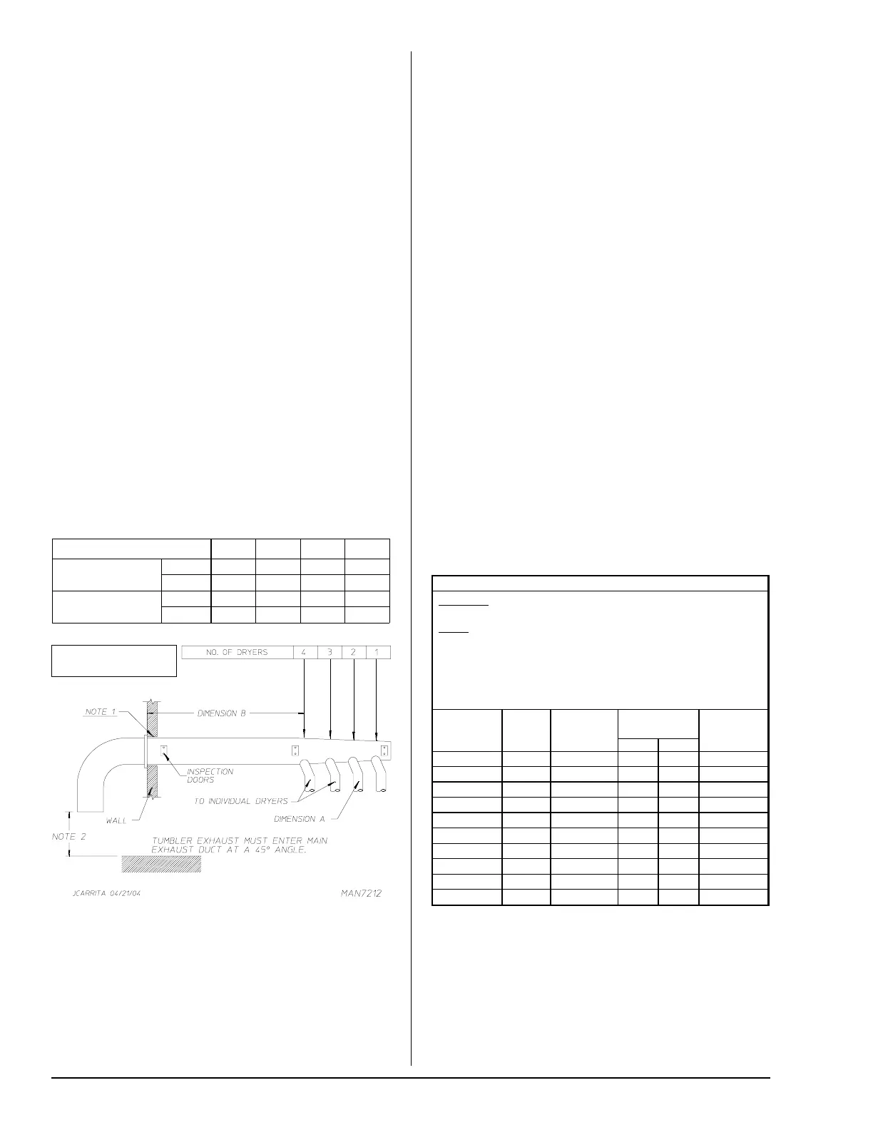
NUMBER OF DRYERS 4 3 2 1
MINIMUM CROSS-
SECTIONAL AREA
SQ IN 615 455 315 200
SQ CM 3967 2935 2032 1290
MINIMUM ROUND
DUCT DIAMETER
IN 28 24 20 16
CM 71 61 50 40
Electrical Information _______________
Electrical Requirements
It is your responsibility to have all electrical connections
made by a properly licensed and competent electrician to
assure that the electrical installation is adequate and
conforms to local and state regulations or codes. In the
absence of such codes, all electrical connections, material,
and workmanship must conform to the applicable
requirements of the National Electrical Code ANSI/NFPA
NO. 70-LATEST EDITION or in Canada, the Canadian
Installation Codes CAN/CGA-B149.1-M91 (Natural Gas) or
CAN/CGA-B149.2-M91 (L.P. Gas) or LATEST EDITION.
IMPORTANT: Failure to comply with these codes or
ordinances, and/or the requirements stipulated in this
manual can result in personal injury or component failure.
NOTE:
Component failure due to improper installation will
void the warranty.
Each dryer should be connected to an independently
protected branch circuit. The dryer must be connected with
copper wire only. Do not use aluminum wire, which could
cause a fire hazard. The copper conductor wire/cable must
be of proper ampacity and insulation in accordance with
electric codes for making all service connections.
NOTE:
The use of aluminum wire will void the warranty.
Wiring diagrams are affixed to the inside at the top front
control door and the rear upper back guard/panel.
Electrical Service Specifications
Gas and Steam Models Only
NOTE 1 Opening must be 2-inches (5.08 cm) larger than the duct (all the
way around). The duct must be centered within this opening.
NOTE 2 Distance should be 2 times the diameter of the duct to the nearest
obstruction.
NOTE:
When the exhaust ductwork passes through a
wall, ceiling, or roof made of combustible materials, the
opening must be 2-inches (5.08 cm) larger than the duct
(all the way around). The duct must be centered within
this duct.
IMPORTANT: For extended ductwork runs, the cross
section area of the ductwork can only be increased to an
extent. Maximum proportional ductwork runs cannot
exceed 20 feet (6.09 meters) more than the original
limitations of 20 feet (6.09 meters) with two elbows.
When the ductwork approaches the maximum limits as
noted in this manual, a professional HVAC firm should be
consulted for proper venting information.
Exhaust back pressure measured by a manometer/
magnehelic in the exhaust duct must be no less than 0
and must not exceed 0.3 in WC (0.74 mb).
NOTE: It is recommended that exhaust or booster fans
not be used in the exhaust ductwork system except where
necessary to maintain exhaust back pressure (in the
exhaust duct) between zero and 0.3 inch water column.
Where employed, booster fans must not activate the dryer
airflow proving switch (sail switch) when the dryer is not in
operation.
The ductwork should be smooth inside with no projections
from sheet metal screws or other obstructions, which will
collect lint. When adding ducts, the duct to be added should
overlap the duct to which it is to be connected. All ductwork
joints must be taped to prevent moisture and lint from
escaping into the building. Inspection doors should be
installed at strategic points in the exhaust ductwork for
periodic inspection and cleaning of lint from the ductwork.
Multiple Dryer Venting 16-Inch (40.64 cm)
Diameter Minimum Exhaust Connections at Common Duct
A = 48-3/4” (123.82 cm)
B = 20 feet (6.09 meters)
* 3-Wire is available. 3/26/15
ELECTRICAL SERVICE SPECIFICATIONS (PER DRYER)
IMPORTANT:
NOTES
: A.
B.
C.
208 VAC AND 230/240 VAC ARE NOT THE SAME. When ordering,
specify exact voltage.
When fuses are used they must be dual element, time delay, current
limiting, class RK1 or RK5 ONLY. Calculate/determine correct fuse
value, by applying either local and/or National Electrical Codes to
listed appliance amp draw data.
Circuit breakers are thermal-magnetic (industrial) motor curve type
ONLY. For others, calculate/verify correct breaker size according to
appliance amp draw rating and type of breaker used.
Circuit breakers for 3-phase (3ø) dryers must be 3-pole type.
SERVICE
VOLTAGE
PHASE
WIRE
SERVICE
APPROX.
AMP DRAW
CIRCUIT
BREAKER
60 Hz 50 Hz
208 3ø 3 14 — 20
220 3ø 3 — 11 15
230 3ø 3 13 — 15
240 3ø 3 12 11 15
380 3ø 4* —6 15
400 3ø 4* —6 15
416 3ø 4* —6 15
440 3ø 3 7 — 15
460 3ø 3 7 — 15
480 3ø 3 7 — 15