113375-16 Telephone 01422 822282 21
Data Label Information ______________
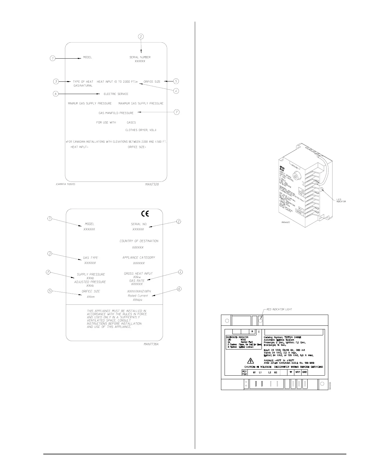
Standard Label
Procedure for Functional Check
of Replacement Components ________
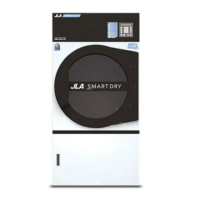
For Heat Control Module Ignition Circuit
For Models with Johnson Controls
DSI Module (G760)
Theory Of Operation
Start the drying cycle. When
the gas burner ignites within
the chosen trial for ignition
time (6-seconds), the flame
sensor detects gas burner
flame and signals the DSI
module to keep the gas valve
open … as long as there is a
call for heat. The DSI
module will “LOCKOUT” if
the gas burner flame is not
sensed at the end of the trial
for ignition period. The trial for ignition period will be repeated
for a total of three retries/trials (the initial try and two more
retries/trials). If the flame is not sensed at the end of the
third retry/trial (inter-purge period of 30-seconds) the DSI
module will “LOCKOUT” (L.E.D. flashes).
A steady L.E.D. indicator indicates normal operation.
No L.E.D. indicator indicates a power or an internal failure
has occurred.
For Models with HSI Module
Start the drying cycle.
The HSI will turn on, and after approximately 4-seconds the
ignitor will shut off and the gas valve will be energized.
Ignition (flame) should now be established.
With the burner flame on, remove the flame sensor wire
from the S2 terminal of the HSI module. The burner flame
must shut off immediately.
CE Label
4. Heat Input (For Gas Dryers) – This describes the heat
input in British thermal units per hour (Btu/hr) or kilowatts
(kW).
5. Orifice Size (For Gas Dryers) – Gives the number drill
size used.
6. Electric Service – This describes the voltage and
current rating for a particular model.
7. Gas Manifold Pressure (For Gas Dryers) – This
describes the manifold pressure taken at the gas valve
tap.
When contacting JLA, certain information is required to
ensure proper service/parts information from JLA. This
information is on the data label that is affixed to the rear
upper left back area of the dryer, which can be viewed either
through the openings in the dryer’s back panel/guard, or by
removing this back panel/guard. When contacting JLA,
please have the model number and serial number available.
1. Model Number – This describes the style of dryer and
type of heat (gas, electric, or steam).
2. Serial Number – Allows the manufacturer to gather
information on your particular dryer.
3. Type of Heat – This describes the type of heat for
your particular dryer, gas (either natural gas or L.P. gas),
electric, or steam.