iii Installation procedures
Refer to the drawing in i for correct wheel balancer
positioning. If the wheel balancer needs securing,
we recommend xing elements with a diameter of
8 mm, quality 8.8 or higher.
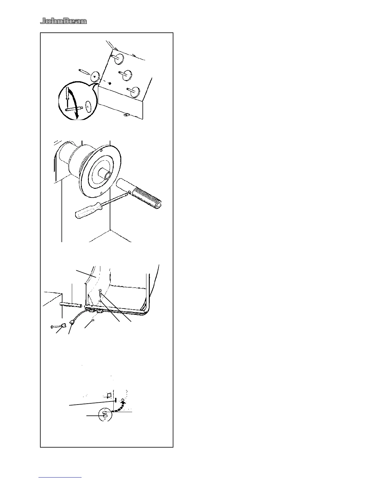
• Unpack the 4 threaded accessory support studs
and the support plates.
• Refer to Figure iii-1. Fit the 4 threaded accessory
support studs and the plates.
• Clean the stub shaft and the hole in the main shaft.
• Refer to Figure iii-2. Position the stub shaft.
• Use a pin for screwing.
• Put the clamping devices on the accessory studs.
• Refer to Figure iii-3.
The measuring run is started by closing the wheel
guard (code C 13).
The wheel is braked on lifting the wheel guard
during a measuring run (code C 5).
Fig. iii-3
Slide the wheel guard (1) on the arbor (2) and raise
it until the fastening holes of wheel guard and wheel
guard arbor coincide.
Insert the M10 setscrew (3) with washer (4) from
below, and tighten the hexagon nut (5) and washer.
Connect the plug of the cable (6) with the connector
of the machine (7) which is projecting out of the
opening in the machine cabinet.
Place the plugs loosely inside the machine through
the hole in the machine cabinet.
Caution:
Since the cable is moved during opening and closing
the wheel guard, it must be passed in the band (8, Fig.
iii-3a) under the wheel guard.