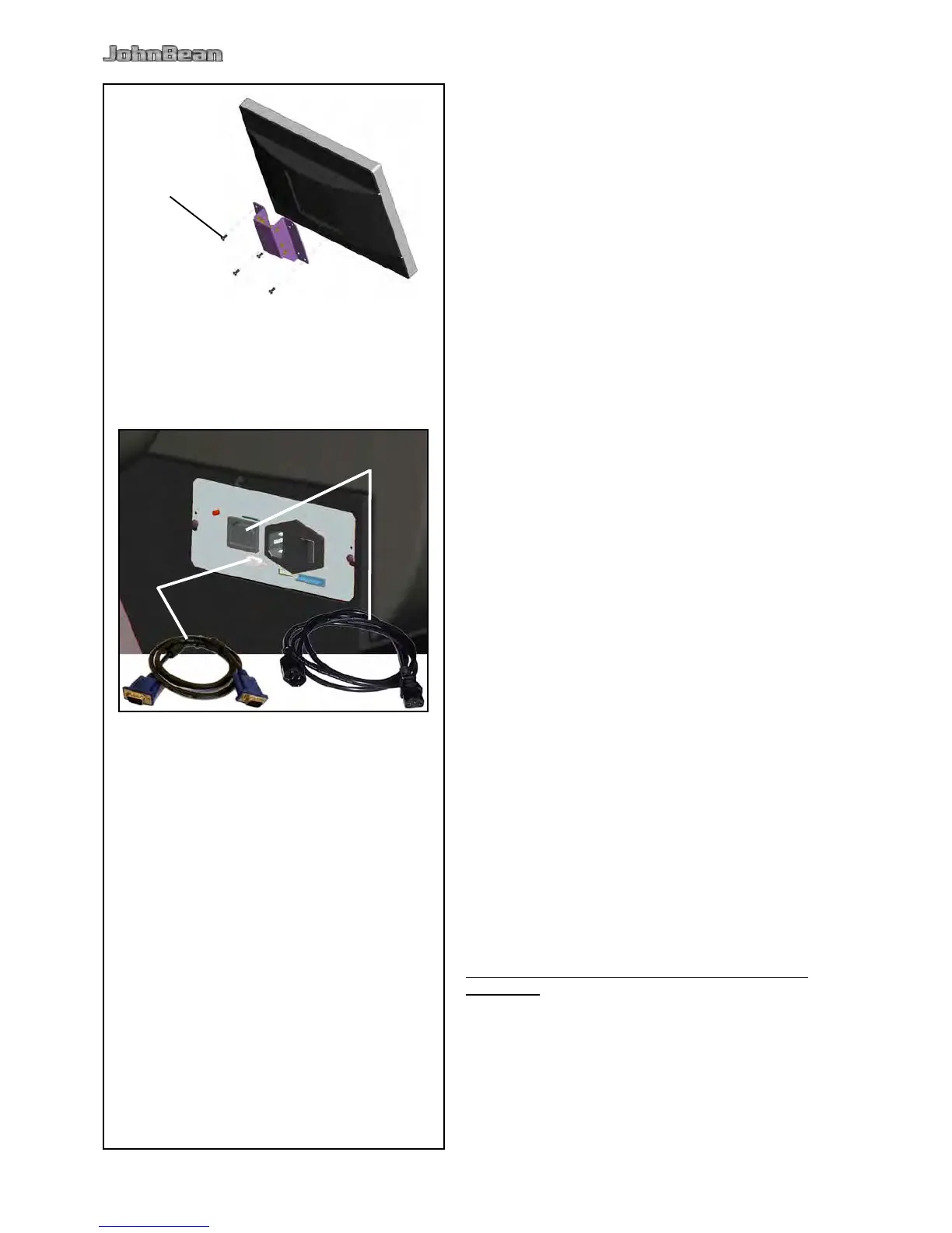
Fig. iii-4 Fitting the monitor
The 4 screws needed (M4x10) to x the VESA support
to the monitor are part of the kit supplied.
Fig. iii-5 Connection of monitor and PC
Caution
Before connecting the electronic cables turn off the
mains switch.
Insert the monitor connector into the right socket
(item 1) of the embedded unit.
Insert the monitor main connector into the socket
(item 2).
• Balance a wheel to less than 5 grams (0.25 oz.) per
plane.
• Perform a User Calibration.
6.2.
(Following applies only if a unit is installed by a service
Technician)
• Show and explain the Safety Booklet.
• Show the operator how to switch the unit on and
off.
• Show the operator how to perform an emergency
stop.
• Show the operator how to select a wheel type, enter
data and apply a weight.
• Balance a wheel to less than 0.25 oz. (5 grams) per
plane.