898841-UIM-B-0113
14 Johnson Controls Unitary Products
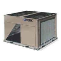
SECURING OUTDOOR UNIT TO SLAB OR FRAME
If the outdoor unit is installed on a field-provided slab or frame, use lag
bolts or equivalent to secure the outdoor unit to the slab or frame.
SECTION XVI: OUTDOOR UNIT WIRING
CONNECTIONS
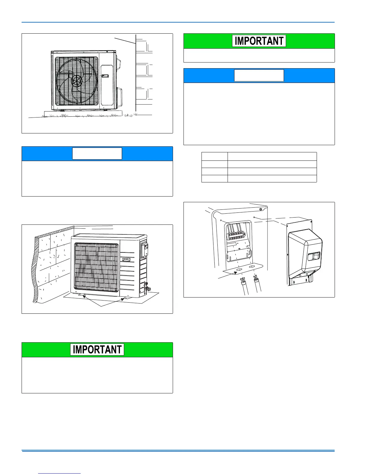
1. Remove outdoor unit access panel.
2. Route all wiring to outdoor unit through the wire routing plate.
3. Connect the control wiring and power supply wiring to the outdoor
unit wiring terminals according to the figures shown in this section.
4. The unit must be grounded according to local codes.
5. Fasten the power supply cord and control wiring with cord clamp.
6. Secure wiring using built-in wire strain relief.
7. Install the outdoor unit access panel back.
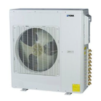
FIGURE 29: Outdoor Unit Installation
This system contains both refrigerant and oil. Some rubber roofing
material may absorb oil. This will cause the rubber to swell when it
comes into contact with oil. The rubber will then bubble and could
cause leaks. Protect the roof surface to avoid exposure to refrigerant
and oil during service and installation. Failure to follow this notice
could result in damage to roof surface.
FIGURE 30: Outdoor Unit Slab or Frame Installation
In the United States, wiring must conform with current local codes
and the current National Electric Code (NEC). In Canada, wiring
must conform with current local codes and the current Canadian
Electrical Code (CEC).
The main system circuit breaker or disconnect should be sized per
unit requirements and should be installed adjacent to outdoor unit.
BUILDING STRUCTURE
GROUND
LEVEL
Install unit level or maintain slope tolerance of 2 degrees
( or 2 inches per 5 feet [50 mm per 1.5 m] away from building structure.
FOUR FIELD PROVIDED ANCHOR BOLTS
Mis-wiring could damage unit or cause communication errors
between indoor and outdoor unit.
• Refer to unit nameplate for minimum circuit ampacity and maxi-
mum overcurrent protection size
• Local codes may require a disconnect between the indoor and out-
door units
• The main system circuit breaker and outdoor unit disconnect
switch should be sized per local codes and unit requirements
• Stranded wire must be used to connect the outdoor unit to the
indoor unit. The stranded wire is necessary to ensure proper sys-
tem communication and operation.
• Make sure you use an approved circuit breaker or switch
Model Fuse or Circuit Breaker Capacity
9K & 12K 20A
18K & 24k 25A
30K & 36k 30A
FIGURE 31: Outdoor Unit Electrical Connections
ROUTE WIRES
THROUGH
ROUTING
PLATE
ACCESS PLATE